Introduction: Gas Valves & Regulation in Field Service
Gas valves and regulation systems are the backbone of reliable HVAC operations, yet field failures remain a leading cause of system downtime. With over 35 years of industrial equipment distribution experience, 3G Electric has supported HVAC contractors across diverse climates and applications. This guide focuses on practical troubleshooting and repair techniques that you can implement immediately in the field—moving beyond basic installation to address real-world failure scenarios.
Understanding the internal mechanics of gas valve failures, recognizing diagnostic signals, and knowing when to service versus replace components can significantly reduce callout costs and improve customer satisfaction. This article distills field-proven strategies that experienced contractors use to diagnose problems quickly and restore system operation.
Section 1: Diagnostic Framework for Gas Valve Failures
Establishing Baseline Pressure Readings
The first step in any gas valve diagnosis is establishing accurate baseline pressure measurements. Begin by identifying two critical measurement points: inlet pressure (supply side) and outlet pressure (load side). Use a certified pressure gauge with 0–10 mbar range for most residential HVAC applications, or 0–6 bar for commercial systems.
Connect your gauge upstream of the valve assembly to record inlet pressure under no-load conditions. Document this value—it should match the equipment manufacturer's specification, typically 20–25 mbar for residential natural gas systems. Next, measure outlet pressure while the burner fires. A pressure drop greater than 10% indicates potential valve restriction or regulator drift.
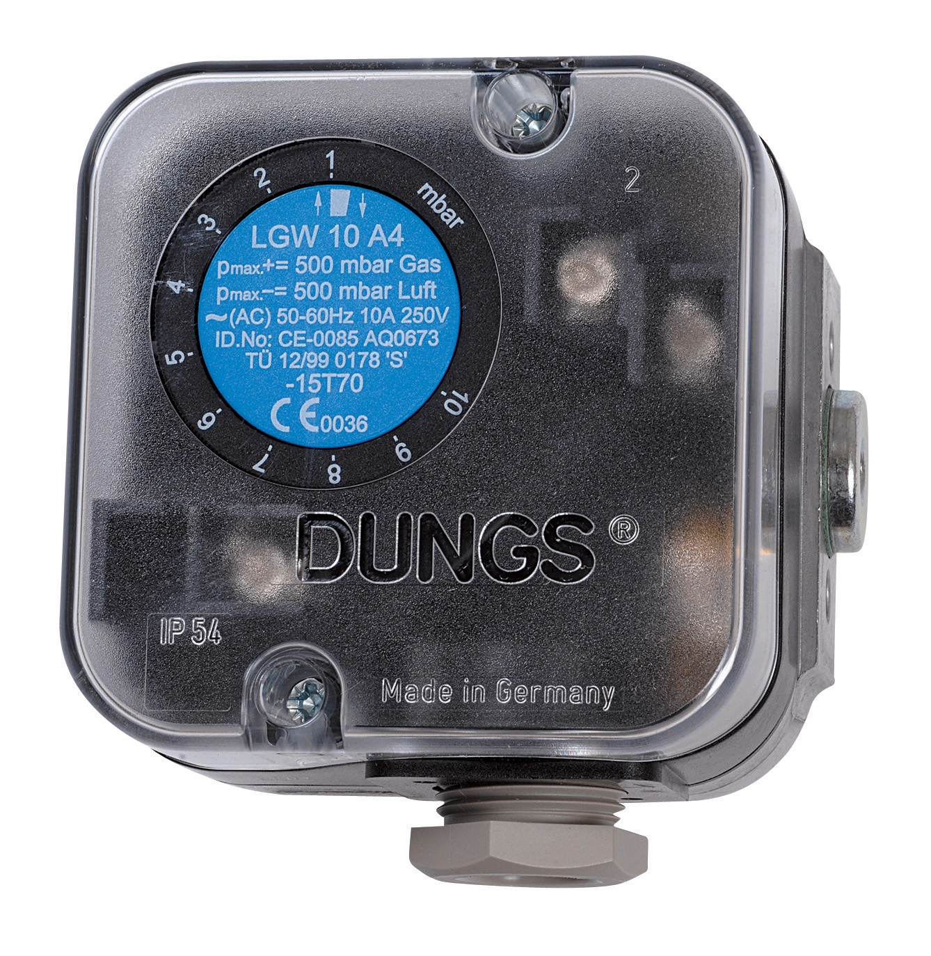
The DUNGS Pressure Switch LGW 3 A2 provides continuous differential pressure monitoring across your entire regulation system. This 0.4–3 mbar device integrates G 1/4 connections directly into your manifold, eliminating manual gauge connections during service calls. The switch's dual NO and one NC contact configuration allows you to trigger alarms when pressure differential exceeds safe operating ranges—critical for identifying regulator creep before it affects combustion efficiency.
Reading Pressure Decay Patterns
When inlet pressure is stable but outlet pressure drops during operation, you're observing real-time regulator behavior. Healthy regulators maintain consistent outlet pressure regardless of inlet fluctuations (within design limits). Rapid pressure decay indicates:
- Internal diaphragm rupture: Outlet pressure drops immediately when burner ignites
- Seat leakage: Slow, gradual pressure loss over 30–60 seconds
- Spring fatigue: Outlet pressure drifts upward with time, then stabilizes
Measure the pressure decay rate: isolate the load by closing the manual shutoff valve downstream of the regulator. If outlet pressure drops without a load present, the regulator is leaking internally. If pressure remains stable with the load isolated but drops when the load is connected, the valve is responding correctly to demand—this is normal operation, not a failure.
Identifying Visual and Auditory Clues
Before connecting gauges, observe the system during operation:
- Hissing or whistling from the regulator vent hole indicates excessive pressure (spring compressed too far)
- Flame instability with intermittent yellow tips suggests irregular gas flow, pointing to valve hunting (oscillation) or seat wear
- No ignition despite gas supply indicates shut-off valve closure, stuck poppet, or complete electrical failure
- Visible corrosion around the regulator body suggests moisture ingress—common in coastal or humid HVAC applications
Section 2: Common Failure Modes and Field Repair Strategies
Solenoid Valve Coil Failures
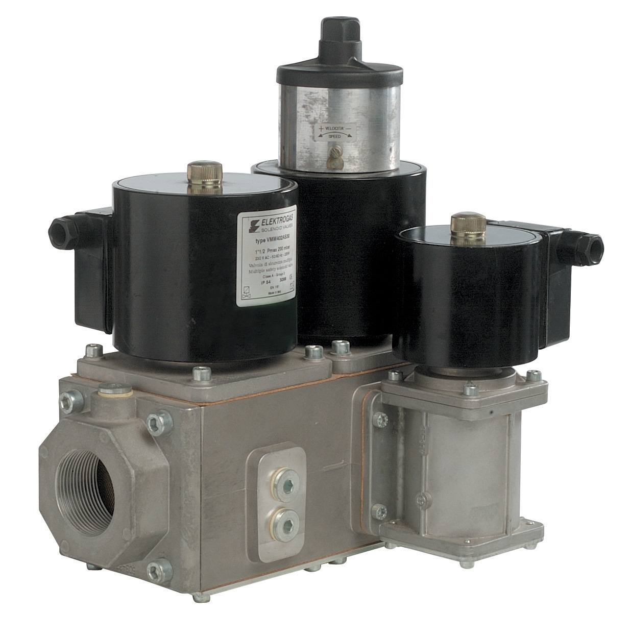
Solenoid valves are electromagnetically controlled shut-off devices essential for safety interlocks. The Elektrogas Multiblock VMM255AF01 is a precision solenoid assembly rated DN20–DN80 with integrated bypass valve for controlled opening. In field service, coil failures present predictably:
Open coil failure (zero continuity): The electromagnet cannot energize. Measure coil resistance using a multimeter—standard industrial coils read 2–15 ohms depending on design. Zero reading confirms open circuit. Replacement is the only solution; do not attempt rewinding in the field.
Coil short-to-ground: Resistance drops below 0.5 ohm. The control circuit's safety relay will lock out the system. Test by isolating the coil and re-energizing the circuit. If the lockout clears, coil replacement is required.
Mechanical stiction: The solenoid plunger sticks in the seated position. Apply 24V DC power and listen for a click. If the plunger doesn't move, tap the solenoid body gently with a plastic mallet while power is applied. If it still doesn't respond, soak the plunger area with penetrating oil for 15 minutes and retry. Persistent stiction requires replacement—internal debris cannot be cleaned reliably in the field.
Regulator Seat and Seal Wear
Regulator seats wear over time as gas flows across the seal. This produces characteristic symptoms: flame height varies without adjustment, or the system operates at higher outlet pressure than design specification. Examine the regulator's adjustment spring:
- Spring pre-compression too high: Turn the adjustment screw counterclockwise ¼ turn, then measure outlet pressure. Repeat until pressure matches the design setpoint (typically stamped on the regulator body)
- Seat erosion: If outlet pressure continues rising even with spring decompression, the seat is worn. Seat damage allows gas to escape around the seal, and the regulator compensates by tightening the spring—a losing battle
For replaceable-cartridge regulators, seat replacement is straightforward. Remove the adjustment cap and spring assembly, then unscrew the seat cartridge (typically a ½-inch hex). Install the replacement and reassemble. For welded regulators, replacement is the only option.
Diaphragm and Spring Fatigue
The regulator diaphragm flexes thousands of times per operating cycle. Fatigue cracks develop at stress points, usually near the diaphragm edge where it seats against the regulator housing. Symptoms include:
- Outlet pressure that cannot be stabilized at the setpoint
- Outlet pressure that suddenly drops to near-zero when ignition occurs
- Water droplets present in the regulator vent line (diaphragm rupture allows condensation to enter)
Diaphragm replacement requires complete regulator disassembly. Order a regulator rebuild kit specific to your model—it contains the diaphragm, seals, and spring. Follow the manufacturer's service manual precisely; improper spring compression during reassembly will cause immediate recalibration drift.
Pressure Relief Valve Stiction
Relief valves protect downstream components by venting excess pressure to atmosphere. When the internal poppet sticks in the seated position, system pressure can exceed design limits, causing damage downstream. Tap the relief valve body sharply with a rubber mallet while observing your pressure gauge. If pressure suddenly vents, the poppet moved—this indicates temporary stiction, not permanent failure.
For persistent stiction, soak the valve bonnet area with penetrating oil and allow 20 minutes of soak time. Tap again. If the valve remains stuck, replace it. Do not attempt to force the poppet or drill into the valve body—these interventions create internal damage that guarantees failure.
Section 3: In-Field Testing and Validation Procedures
The Closed-Loop Pressure Isolation Test
Before declaring a regulator or solenoid valve faulty, isolate it completely from the system load. This test confirms whether the component itself is defective or whether downstream blockage is creating back-pressure.
Procedure:
1. Close the manual shutoff valve immediately downstream of the component under test
2. Connect a pressure gauge to the component's outlet port
3. Slowly open the upstream isolating valve to restore inlet pressure
4. Record the outlet pressure with the downstream valve closed
5. Slowly crack open the downstream valve to create a small load
6. Observe whether outlet pressure changes with load
A healthy regulator maintains constant outlet pressure regardless of load (within its design pressure recovery specification, typically ±0.5 mbar). A defective regulator shows erratic pressure swings or cannot maintain setpoint pressure with load applied.
The Flame Response Test
Ignite the burner and observe flame response when you momentarily restrict gas flow by partially closing the main gas supply valve. A healthy system shows stable flame height that dips slightly during restriction, then recovers quickly when you release the restriction.
A defective solenoid valve exhibits delayed response: flame takes 2–3 seconds to react to valve movement, or the flame drops to zero before recovering. A defective regulator shows flame overshooting (momentary high spike) as pressure adjusts, then stabilizing. These timing signatures identify which component is failing.
Electrical Continuity Testing for Control Circuits
If the system fails to ignite despite confirming gas supply, test the solenoid coil and ignition switch circuit:
1. Set your multimeter to continuity mode
2. Disconnect the solenoid coil lead from the control board
3. Test between the coil terminal and ground—you should read continuity (low resistance)
4. If no continuity, the coil is open and must be replaced
5. If continuity exists, reconnect the coil and test the ignition switch circuit: press the ignition button while measuring voltage at the solenoid coil terminal—you should see 24V DC during button press
No voltage at the coil indicates a failed control relay or broken wiring, not a faulty solenoid. A failed relay is typically more cost-effective to replace than replacing a solenoid that is functioning correctly.
Section 4: Service Component Selection and Replacement Procedures
High-Pressure Hose Assemblies in Gas Service
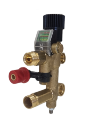
Gas regulation systems often include high-pressure hoses connecting the regulator to the burner manifold. These hoses experience thermal cycling and vibration stress. The Pratissoli High Pressure Sewer Cleaning Hoses ZT12B0800606 and Pratissoli ZT16B0805757 represent Italian-engineered hydraulic hose assemblies—the same quality standards apply to gas service hoses used in industrial HVAC applications.
When replacing a gas service hose, size selection is critical. Measure the inner diameter of the existing hose connection, then verify the maximum operating pressure rating (usually stamped on the hose). Order replacement hoses with identical diameter and pressure rating. Pre-formed hose assemblies with factory fittings reduce field connection time and eliminate risk of improper swaging.
Inspect hose condition annually in high-vibration applications such as rooftop-mounted HVAC units. Look for:
- Cracks or abrasion in the outer rubber cover
- Leaking at hose-fitting connections (indicates internal degradation)
- Hose that appears flattened or kinked (restricts flow)
Pressure Regulating Valves for Precision Control
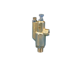
For applications requiring stable outlet pressure with varying inlet conditions, the Interpump PRESS.REG.VALVE KR92 offers precision control rated to 90 bar maximum with 11 L/min flow capacity. This cartridge-style regulator integrates into manifold blocks, simplifying installation and reducing connection points where leaks can develop.
When specifying a replacement regulator:
1. Confirm pressure setpoint: The original regulator body should display the setpoint in mbar or bar. Specification mismatch causes immediate flame control issues
2. Verify flow capacity: The replacement must handle the system's maximum gas demand under peak load. Calculate this by measuring the gas line diameter, inlet pressure, and outlet pressure under full-fire conditions
3. Check connection size: Gas regulators use G (ISO) threads or NPT (US) threads. Verify the existing manifold threading before ordering
4. Confirm environmental compatibility: Coastal applications require stainless steel internals; standard brass corrodes in salt-air environments
Conclusion: Building HVAC Reliability Through Systematic Troubleshooting
Gas valve and regulation system failures follow predictable patterns. By implementing systematic pressure testing, recognizing diagnostic signatures, and knowing which components can be repaired versus replaced, HVAC contractors significantly reduce diagnostic time and customer downtime.
3G Electric's 35+ years of industrial equipment distribution experience supports contractors with field-proven components and technical resources. When you encounter a regulation system failure, start with baseline pressure readings, apply the isolation testing procedures outlined above, and consult component datasheets before making replacement decisions. This methodical approach transforms troubleshooting from guesswork into reliable diagnosis.