Understanding Controls & Safety in Flame Detection Systems
Flame monitoring and safety relay coordination form the critical backbone of modern HVAC burner Controls & Safety systems. When these components fail or respond too slowly, the entire combustion sequence collapses—resulting in lockouts, failed ignition cycles, and frustrated service calls. Drawing on 35+ years of experience supporting industrial equipment distributors and HVAC contractors worldwide, 3G Electric recognizes that technicians often struggle to distinguish between genuine flame detection failures and false lockouts caused by relay response time mismatches.
This guide focuses on a practical comparison between ultraviolet (UV) and ionization flame detection methods, explains how safety relays interact with flame sensors, and provides step-by-step troubleshooting procedures that contractors can implement immediately. Rather than replacing components blindly, you'll learn to diagnose the root cause—whether it's a degraded sensor window, incorrect relay timing, electrical interference, or sensor signal strength loss.
Section 1: UV Flame Detection vs. Ionization Monitoring—Comparative Strengths and Failure Modes
How UV and Ionization Detection Work
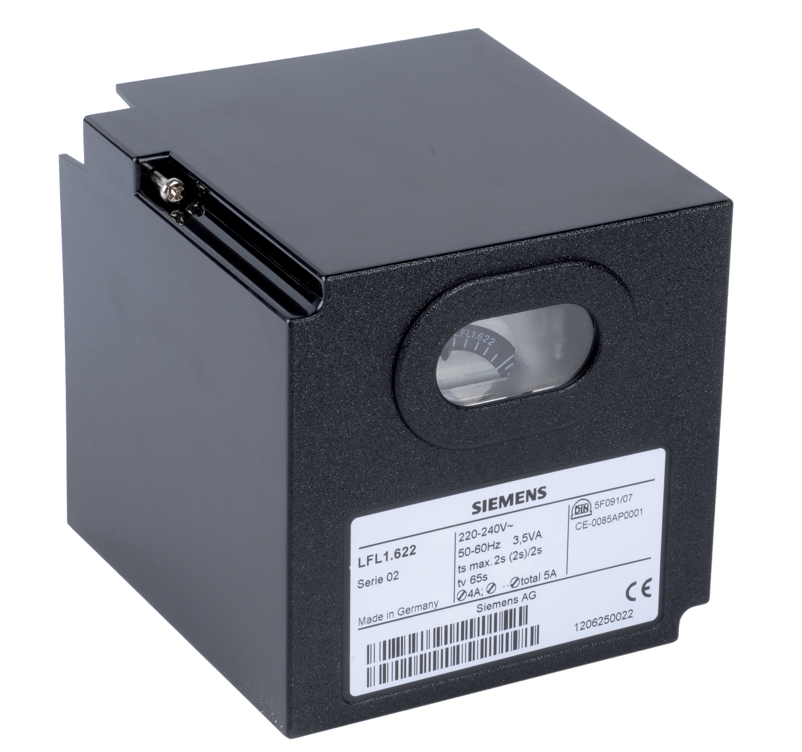
Ultraviolet (UV) flame sensors use solid-state photodiodes to detect the UV radiation emitted by a flame in the 185–260 nm wavelength range. These sensors operate independently of fuel type and flame ionization characteristics, making them reliable across gas, oil, and dual-fuel applications. The Siemens LFL 1.622 safety control unit exemplifies modern UV detection, offering reliable flame monitoring for medium to high-power burners with direct UV sensing capability.
Ionization flame detection works differently: a small probe positioned in the flame detects the electrical conductivity created by ionized gas molecules. When combustion occurs, free ions allow current flow through the probe to ground. This method is fuel-flexible and cost-effective, but performance depends on flame temperature, electrode geometry, and probe cleanliness. The Brahma Relay CM 31 F TW10/TS5 incorporates ionization flame monitoring for gas burner applications, providing intermittent operation support and proven reliability in industrial flame detection.
Failure Mode Comparison
UV Sensor Failures:
- Optical window fouling: Dust, soot, or combustion deposits accumulate on the quartz window, reducing light transmission and signal strength. Unlike ionization probes, UV windows cannot be self-cleaning.
- Photodiode degradation: Exposure to excessive heat or electrical stress reduces the photodiode's sensitivity over time, causing intermittent flame loss signals.
- Ambient UV interference: Fluorescent lights, LED fixtures, or direct sunlight can trigger false flame detection if the sensor views non-flame UV sources.
- Cable shielding breakdown: High-voltage transients from ignition systems or solenoid coils can corrupt the low-voltage UV sensor signal if cables lack proper shielding.
- Probe carbon buildup: Conductive carbon deposits bridge the probe gap, creating false flame signals even during shutdown.
- Probe wear: Repeated ignition cycles oxidize the probe electrode, increasing resistance and reducing signal amplitude.
- Spark interference: Ignition sparks can induce transient currents in the probe circuit, causing erratic flame detection until the relay timing is adjusted.
- Fuel-dependent performance: Low-flame-temperature fuels or fuels with poor ionization characteristics may produce weak signals that border on the relay's detection threshold.
Contractor Selection Guidance
For HVAC contractors working primarily with natural gas burners in stable indoor environments, ionization detection offers cost advantages and proven simplicity when maintained regularly. UV detection shines in applications with frequent fuel changes, outdoor installations, or environments with fluorescent lighting and potential interference.
Section 2: Safety Relay Response Times and Lockout Integration—Timing Mismatch Diagnosis
How Safety Relays Coordinate with Flame Sensors
A burner safety relay receives the flame sensor signal and must make a critical decision within milliseconds: "Is there a stable flame, or should I trigger a shutdown?" The relay's firmware (or mechanical design in older units) defines:
1. Flame recognition time (FRT): How long the relay waits after ignition before accepting the flame signal as valid (typically 0.5–2 seconds).
2. Flame loss delay: How long the relay allows flame signal loss before triggering shutdown (typically 0.1–0.5 seconds to prevent nuisance trips from voltage dips).
3. Lockout response: Whether the relay enters manual or automatic reset mode after detecting loss of flame.
The Kromschroder Relay BCU 570WC1F1U0K1-E supports both direct ignition and intermittent/continuous pilot modes, with configurable timing parameters that must align with the specific flame sensor and ignition system in use. Mismatch between relay timing and sensor response creates two failure patterns:
Pattern A: Premature Flame Loss Detection
The relay's flame loss delay is set shorter than the time required for the flame sensor to produce a stable signal. Result: The burner ignites, the sensor begins to respond, but the relay interprets the signal ramp-up as flame loss and shuts down. Contractors observe repeated ignition attempts followed by lockout on the first or second cycle.
Pattern B: Delayed Flame Recognition
The flame recognition time is set longer than necessary, or the relay waits for an artificially high signal threshold. Result: A healthy flame is present, but the relay delays acceptance, sometimes long enough that the ignition circuit times out. Burners cycle repeatedly before establishing stable operation.
Diagnostic Procedure: Flame Signal Strength and Relay Timing Alignment
Step 1 – Baseline Measurement
With the burner safely shut down, use a digital multimeter set to AC voltage mode. Connect the meter across the flame sensor output terminals (consult the relay wiring diagram). Set the meter to the 2V or 10V AC range to capture low-level signals accurately.
Step 2 – Measure During Ignition
Initiate a normal ignition cycle. As the igniter sparks, observe the multimeter reading:
- A healthy UV sensor typically shows 1–3V AC within 0.3 seconds of spark initiation.
- A healthy ionization probe typically shows 0.5–1.5V AC once the flame establishes.
- If the meter shows less than 0.3V AC, suspect sensor fouling or cable damage.
- If no signal appears after 2 seconds, the sensor may be failed or disconnected.
Open the relay manual or contact the manufacturer for the minimum detection threshold (often 0.5–1V AC). If your measured signal is within 20% of the threshold, the system is operating on the margin and prone to nuisance lockouts. Clean the sensor or replace it if degraded.
Step 4 – Test Flame Loss Response
Once the burner achieves stable operation, observe the time between flame signal presence and ignition shutdown:
- Gently blow out the flame or reduce input to simulate flame loss.
- The relay should trigger shutdown within 0.1–0.5 seconds (check the manual for the specified delay).
- If shutdown is delayed beyond 1 second, the relay's flame loss delay may be mis-configured or the relay may be malfunctioning.
Record the signal voltage, recognition time, and loss delay for the specific burner model and sensor type. Use this as a baseline for future service calls. If the same burner model experiences repeated lockouts at a different customer site, compare the baseline; if signal voltage is lower by more than 0.5V, cleaning or sensor replacement is indicated.
Safety Relay Selection for HVAC Applications
When specifying replacement relays, HVAC contractors should request units with adjustable flame recognition and flame loss timing parameters. The Kromschroder BCU 570WC1F1U0K1-E, compliant with EN 746-2 and EN 676 standards, provides this flexibility. Similarly, the Siemens LFL 1.622 offers configurable timing suitable for burners ranging from small residential units to large commercial systems.
Section 3: Pressure Switch and Flame Sensor Interlock Failures—Sequence Diagnostics
How Pressure Switches Coordinate with Flame Monitoring
Modern HVAC burner safety systems integrate pressure switches (often monitoring gas pressure, air pressure, or draft) with flame sensors to prevent ignition under unsafe conditions. The sequence typically follows this logic:
1. Pre-ignition check: Pressure switches verify that gas supply is present and air/draft conditions are safe.
2. Ignition authorization: Only if pressure conditions are acceptable does the control relay permit spark ignition.
3. Flame verification: The flame sensor must confirm flame presence within the specified recognition time.
4. Pressure stabilization: Operating pressure (flame-on) must stabilize within normal range within 3–5 seconds.
If the flame sensor detects flame but the pressure switch does not confirm normal operating pressure, the relay locks out, preventing continuous operation. This interlock is a safety feature, but diagnostics can be challenging when pressure and flame sensors disagree.
Diagnostic Procedure: Isolating Pressure vs. Flame Signal Failures
Step 1 – Pressure Switch Baseline Test
With the burner off, use a manometer or digital pressure meter appropriate for the gas or air system being monitored. Record the baseline pressure (should be near zero for most HVAC applications when the burner is off).
Step 2 – Monitor Pressure During Ignition
Initiate ignition and observe pressure rise in real-time:
- Pressure should rise within 0.5–1 second of flame establishment.
- Operating pressure should reach and stabilize at the design setpoint (typically 5–20 mbar for gas, depending on the burner model).
- If pressure rises slowly or overshoots the setpoint, suspect a defective pressure regulator (see below).
Simultaneously observe the flame sensor signal (using the voltage method from Section 2) and the pressure response:
- Normal operation: Flame signal rises to 1–3V AC, then pressure rises in parallel.
- Pressure delay with good flame signal: Suggests the pressure transducer or regulator is sluggish. Check for clogged ports or a failing solenoid valve.
- Flame signal loss with good pressure: Suggests the flame sensor or its circuit is faulty; pressure rises correctly because the solenoid and burner are responding, but the flame sensor is not reporting ignition.
The Kromschroder DG 50U/6 pressure switch, rated SIL 3 with Performance Level e, is designed specifically for this coordination. If your baseline diagnostic shows misalignment between flame and pressure signals, the pressure switch may be miscalibrated or the relay's interpretation of the pressure input may be incorrect.
Step 4 – Solenoid Valve and Gas Block Response Check
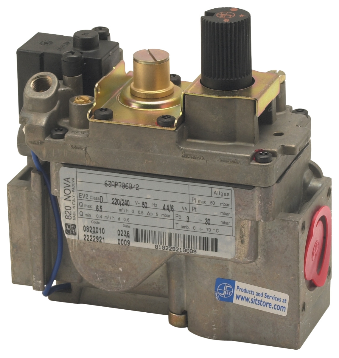
Some pressure delays originate not in the pressure switch, but in the fuel control itself. The Sit Minisit gas block 0710218 incorporates thermoelectric flame supervision and pressure regulation; if this unit's internal valve is sticking, pressure rise will lag flame detection. Apply gentle manual pressure to the gas inlet while observing pressure output to verify the block's response.
Step 5 – Relay Configuration Review
Check the relay manual for the pressure verification delay—some relays intentionally wait 1–2 seconds after flame detection before requiring pressure confirmation, allowing slow-opening solenoid valves time to respond. If your pressure response time exceeds this delay, either the relay timing needs adjustment, or the valve/block requires service.
Common Interlock Scenarios and Solutions
| Symptom | Probable Cause | Solution |
|---------|---|---|
| Flame detected, but relay locks out before pressure stabilizes | Pressure verification delay too short | Adjust relay timing or replace with unit supporting longer delay |
| Pressure rises normally but flame signal is weak | Flame sensor degraded or fouled | Clean sensor window or replace probe |
| Pressure doesn't rise despite flame signal present | Solenoid valve stuck or gas block malfunction | Test solenoid coil resistance; replace or service gas block |
| Pressure and flame both absent; ignition attempts but quits | Gas supply blockage or regulator failure | Check upstream pressure; verify regulator diaphragm; clear any obstructions |
Section 4: Integration and Long-Term Reliability—Best Practices for HVAC Contractors
Preventive Maintenance Schedule
Reduce flame monitoring and relay failures by implementing quarterly inspections for burners in regular service:
- Visual inspection: Remove sensor from burner and examine for soot, carbon, or dust accumulation. UV windows should be clear; ionization probes should be shiny with minimal discoloration.
- Signal strength test: Perform the voltage measurement procedure (Section 2) and compare to baseline. If signal strength has dropped more than 10% since last service, schedule sensor cleaning or replacement.
- Pressure verification: Check pressure switch calibration annually using a calibrated manometer. Verify that the switch activates and deactivates within ±5% of the specified setpoint.
- Relay reset test: Monthly, test the relay's manual reset function (if equipped) to ensure reset switches are responsive and the relay responds correctly to flame loss simulation.
Selecting Complementary Controls and Safety Components
3G Electric, with 35+ years of experience as a distributor of industrial and HVAC equipment, recommends pairing flame sensors with pressure switches and gas blocks from the same manufacturer family when possible. For example:
- Gas block selection: The Sit Minisit gas block 0710218 works well with traditional solenoid valve-based controls and is compatible with both continuous pilot and intermittent ignition systems.
- Relay selection: If using the Sit gas block, pair it with a relay like the Brahma CM 31 F TW10/TS5 that supports ionization detection; the Brahma relay's intermittent operation mode aligns with the Sit block's thermoelectric flame supervision philosophy.
- Pressure monitoring: For burners requiring SIL 3 safety integrity, specify the Kromschroder DG 50U/6 pressure switch alongside the Kromschroder BCU 570WC1F1U0K1-E relay to ensure timing and thresholds are optimized for each other.
Documentation and Troubleshooting Records
Maintain a service log for each customer burner that includes:
1. Installation date and component serial numbers for the relay, flame sensor, pressure switch, and gas block.
2. Baseline measurements: Signal voltage, pressure setpoint, relay recognition time, and flame loss delay.
3. Maintenance history: Dates of cleaning, component replacements, and any configuration changes.
4. Lockout events: Date, time, symptom (e.g., "flame detected, then relay locked on loss of pressure"), and root cause diagnosis.
This record is invaluable when the same burner experiences repeated issues; you can quickly identify whether the problem is a recurring sensor fouling issue (requiring more frequent cleaning schedules or a sensor upgrade) or a systematic timing mismatch (requiring relay reconfiguration).
When to Replace vs. Repair
Use these guidelines to decide whether troubleshooting will resolve the issue or a component replacement is necessary:
- Flame sensor: If cleaning the window or probe restores signal voltage to within 10% of baseline, continue monitoring. If signal remains more than 20% below baseline after cleaning, replace the sensor.
- Pressure switch: If the switch is slow to activate or deactivate (more than ±10% off setpoint), attempt recalibration using the adjustment screw (if available). If adjustment does not help, replace the switch.
- Relay: If the relay is locking out repeatedly despite normal flame and pressure signals, try adjusting the flame recognition or flame loss delay timers (if the relay supports adjustment). If lockouts persist, the relay's internal detection circuit may be faulty; replacement is warranted.
- Gas block or solenoid valve: If pressure response is sluggish even after verifying good signal at the ignition spark, the block's internal valve may be sticking. Clean the valve ports or replace the unit if cleaning does not restore performance.
By following these decision criteria and maintaining detailed records, HVAC contractors can reduce troubleshooting time, improve first-call fix rates, and build customer confidence through transparent, evidence-based service.
Conclusion
Controls & Safety failures in HVAC burner systems often stem from misalignment between flame sensor detection, safety relay timing, and pressure verification—not necessarily from component defects. By understanding the comparative strengths and failure modes of UV and ionization flame detection, mastering the diagnostic procedures for signal strength and timing synchronization, and integrating pressure switch and gas block diagnostics into your troubleshooting workflow, you'll diagnose and resolve the root causes of lockouts and unreliable ignition.
3G Electric's 35+ years of experience as a distributor puts us in a unique position to support HVAC contractors with not only quality components like the Kromschroder BCU 570WC1F1U0K1-E, Brahma CM 31 F TW10/TS5, Sit Minisit gas block 0710218, Kromschroder DG 50U/6, and Siemens LFL 1.622, but also with the knowledge and guidance needed to select, install, and maintain these components for maximum reliability and safety.