Understanding Controls & Safety System Diagnostics
Controls & Safety systems represent the nervous system of industrial HVAC and burner equipment, yet many contractors treat them reactively rather than strategically. With over 35 years of experience distributing industrial equipment across Southeast Asia, 3G Electric has observed that the most successful contractors implement predictive maintenance protocols that catch problems before they cascade into system failures.
A Controls & Safety system integrates multiple components—relay units, pressure switches, flame detection modules, and gas control blocks—that must communicate seamlessly. When one component begins to degrade, subtle signal degradation often precedes catastrophic failure. The difference between an unplanned shutdown costing thousands in emergency service calls and a scheduled maintenance window is often recognizing these early diagnostic indicators.
Southeast Asia's tropical climate adds unique challenges. High humidity, salt spray in coastal facilities, temperature cycling, and dusty industrial environments accelerate component wear. Understanding how these environmental factors interact with your Controls & Safety equipment enables you to implement location-specific maintenance strategies that dramatically improve reliability.
Diagnostic Techniques for Safety Relay and Burner Control Units
Visual and Electrical Inspection Protocols
Begin diagnostics with systematic visual inspection. Look for corrosion on terminal connections, discoloration on relay contacts indicating arcing, and any signs of moisture ingress. In tropical environments, white corrosion on brass components and green oxidation on copper terminals signal moisture problems requiring immediate attention.
The Kromschroder Relay BCU 570WC1F1U0K1-E exemplifies modern burner control relay design, but even premium components require proper environmental protection. When inspecting this relay, check that the mounting location has adequate ventilation to prevent condensation accumulation. Test continuity across terminal pairs using a calibrated multimeter—any deviation from expected resistance patterns suggests internal contact degradation.
Electrical diagnostics should include voltage testing at multiple points in the control circuit. Measure supply voltage at the relay terminals (should match nameplate specification), then test output voltages under both standby and active conditions. Fluctuating voltages often indicate loose connections or oxidized terminal contacts upstream in your control circuit.
Flame Detection System Diagnostics
Flame detection represents one of the most critical safety functions in Controls & Safety systems. The Pactrol Housing P 16 DI CE 400601/V23 flame control module operates at 230V with 12kV ignition output—any degradation in flame signal detection creates serious safety risks.
Test flame detection circuits by:
- Measuring the UV or ionization signal during normal burner operation using an oscilloscope
- Recording baseline signal strength when burner operates cleanly
- Repeating measurements after the burner has accumulated operating hours to establish degradation trends
- Documenting any signal that dips below 60% of baseline strength as a replacement indicator
Clean the flame sensing electrode carefully—mineral deposits from contaminated fuel or poor air quality reduce signal transmission. Use only non-abrasive methods; scratching the electrode surface can create erratic readings. Replace sensing electrodes on a predetermined schedule in high-duty applications rather than waiting for failure.
Safety Pressure Switch Verification
The Kromschroder Pressure switch DG 50U/6 provides critical SIL 3-rated pressure monitoring for burner control applications. Pressure switch diagnostics require precision instruments and careful procedures.
Calibrated pressure gauges must be connected to test points on the burner control system. Record static pressure readings when the burner is off, then under operating conditions. Compare actual readings to switch setpoints documented in the equipment manual. If readings drift beyond ±5% of the original setpoint, the switch requires replacement—degradation will only accelerate.
Test the electrical signal switching independently from pressure calibration. With the burner at steady state, apply gradual pressure increase and observe the exact pressure at which the electrical switch closes (or opens, depending on circuit design). This switching point should be repeatable within 0.5% over multiple cycles. Drifting setpoints indicate internal spring degradation or contaminated wetted surfaces requiring component replacement.
Environmental Factors and Southeast Asia Climate Adaptation
Tropical Climate-Specific Maintenance Strategies
Southeast Asia's high humidity, temperature ranges of 25-35°C with significant daily cycling, and seasonal monsoon moisture create environmental stresses that temperate-zone contractors rarely encounter. Your Controls & Safety diagnostics must account for these conditions.
Implement protective measures including:
- Installing desiccant breathers on all control panel enclosures to manage moisture ingress
- Specifying gasket materials rated for tropical conditions (EPDM typically outperforms nitrile rubber in this climate)
- Increasing terminal connection inspection frequency to monthly intervals in coastal or high-humidity facilities
- Using conformal coating on circuit board assemblies in spray-prone environments
The Siemens Relay LFL 1.622 safety control unit requires special attention in tropical deployments. Schedule flame monitoring electrode inspection at 500-hour intervals rather than 1000-hour intervals typical in temperate zones. Contamination from humid air accelerates electrode surface degradation, reducing signal-to-noise ratios in flame detection circuits.
Preventive Maintenance Scheduling
Develop location-specific maintenance calendars rather than applying generic intervals. For facilities within 10km of coastal saltwater, increase inspection frequency by 50% and plan for more aggressive terminal corrosion treatment. For facilities in high-dust industrial areas, increase air filter changes and implement more frequent visual inspections of relay terminal contacts.
Document maintenance history meticulously. Track which components required service in specific locations, environmental conditions at failure time, and time-to-failure patterns. After 12-18 months of operation, this data enables you to predict likely failure points and schedule preventive replacement before failures occur, maximizing uptime for your customers.
Gas Control Blocks and System Integration Diagnostics
Modulating Valve Performance Monitoring
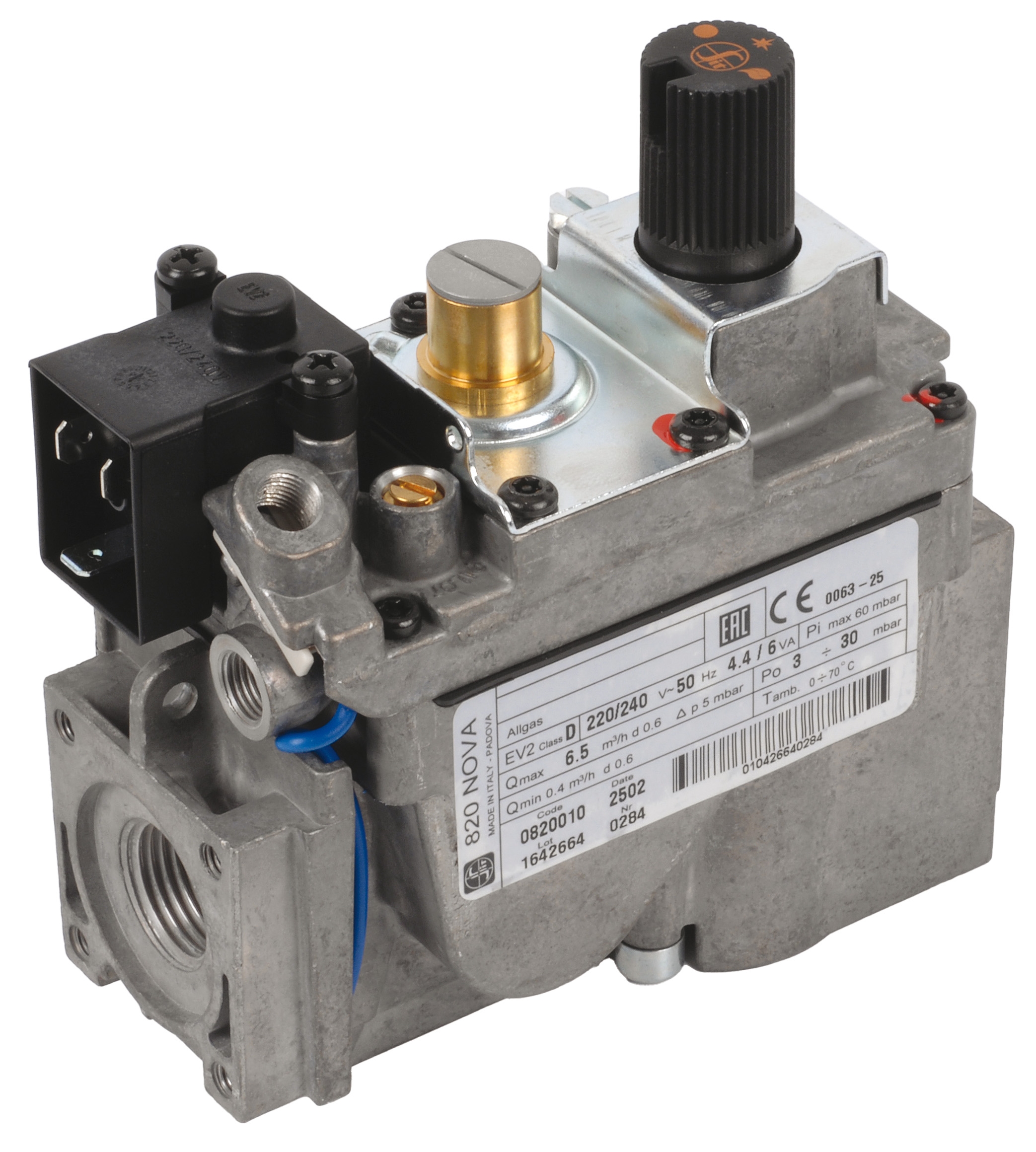
The Honeywell Gas block VK 4105 C 1041 U electric modulating pressure regulator provides precise gas flow control essential for efficient burner operation. Diagnostic monitoring of modulating valves differs significantly from simple on-off solenoid valve testing.
With a calibrated pressure gauge connected to the main outlet pressure test point and a secondary gauge on the pilot feedback line, operate the burner through a complete firing sequence while recording pressure readings:
- Note outlet pressure during full-fire conditions (should match the regulator setpoint specification)
- Observe pressure during modulation down to minimum fire conditions
- Measure pilot feedback pressure response—should track main pressure changes within 2-3 second lag time
- Test the integral pressure relief function by slowly increasing downstream pressure until relief opens
Any hesitation in modulation response, pressure overshoot during load changes, or hunting (repeated cycling) indicates internal valve degradation. Unlike simple replacement of binary components, modulating valve problems often require complete unit replacement rather than field repair, making predictive diagnostics especially valuable.
Control Circuit Integration Testing
Modern Controls & Safety systems integrate multiple components through sophisticated control circuits. Diagnostics must verify that individual components function correctly in isolation AND that they communicate properly within the overall system.
With the burner safely offline and all fuel isolated, apply simulated inputs to the control system:
- Simulate a pressure switch closure by jumpering across its contacts, then verify the relay responds appropriately
- Apply simulated flame signal input to flame detection circuits, confirming modulating valve and other control outputs respond as designed
- Disconnect one pressure switch at a time and verify that safety interlocks prevent dangerous operation
These integration tests reveal wiring faults, incorrect terminal assignments, and degraded signal paths that component-level testing would miss. Integration testing transforms you from a technician who repairs broken equipment to a diagnostician who prevents failures.
Building Contractor Competency in Controls & Safety Diagnostics
Certification and Training Pathways
Controls & Safety systems in Southeast Asia increasingly incorporate components meeting multiple international standards (EN 746-2, EN 676, FM, UL, AGA, GOST-TR). Contractors must understand not just how to test these systems but how compliance requirements influence maintenance procedures.
Pursue technical training specific to your region's equipment standards. Manufacturer-provided training on specific relay models (such as Cromschroder, Siemens, or Honeywell units) provides deeper expertise than generalized HVAC controls courses. Many equipment suppliers offer regional training programs—3G Electric can connect you with manufacturer technical resources and training opportunities throughout Southeast Asia.
Documentation Systems for Diagnostic Excellence
Implement a structured approach to recording diagnostic data:
- Maintain baseline readings (voltage, pressure, signal strength) from initial commissioning
- Record all diagnostic measurements with timestamps and environmental conditions noted
- Establish trending calculations showing rate of change over time
- Flag components for replacement when trending indicates degradation approaching failure thresholds
This documentation transforms sporadic maintenance into strategic asset management. When you can show a customer that Component X is operating at 75% of baseline capacity and trending downward, they understand why preventive replacement makes economic sense. Without documentation, you're asking customers to trust your judgment; with it, you're presenting objective evidence.
Practical Implementation for HVAC Contractors
Transform Controls & Safety diagnostics from intimidating complexity into systematic procedures. Start with the simplest components (pressure switches, visual inspections) and expand to sophisticated diagnostics (modulating valve response testing, flame signal analysis) as your team builds competency.
Invest in proper test equipment: calibrated pressure gauges, digital multimeters, and oscilloscopes rated for the voltages you're testing. Cheap test equipment produces unreliable data that undermines your entire diagnostic program. Quality instruments pay for themselves through improved diagnostics and customer confidence.
Partner with a reliable industrial equipment distributor like 3G Electric that understands Controls & Safety systems throughout Southeast Asia. We can provide not just components like the Kromschroder Relay BCU 570WC1F1U0K1-E, pressure switches, and Siemens safety units, but also technical guidance, documentation resources, and connections to manufacturer training. Over 35 years of experience means we've seen the patterns, understand regional challenges, and can help you develop diagnostics protocols that work in your market.
Start implementing predictive maintenance immediately. The contractors who will thrive in Southeast Asia's industrial HVAC market are those who shift from reactive "fix it when it breaks" approaches to proactive diagnostics that prevent failures before they occur. Your reputation for reliability will differentiate you in a competitive market.