Understanding Controls & Safety in Industrial Burner Systems
Controls & Safety components are the backbone of any industrial burner installation. These systems monitor flame detection, manage fuel flow, prevent unsafe ignition sequences, and provide emergency shutdown capability. For maintenance teams responsible for burner installations across Singapore's industrial sector, understanding the proper installation and commissioning procedures is essential to meet regulatory requirements and ensure safe, efficient operation.
With over 35 years of experience distributing industrial equipment throughout Asia-Pacific, 3G Electric has supported thousands of maintenance teams through proper installation and commissioning of control systems. This guide translates that experience into practical procedures your team can apply immediately.
Section 1: Pre-Installation Planning and Component Verification
Before any Controls & Safety component touches your burner system, verification and planning are critical. Improper installation leads to nuisance lockouts, safety violations, and costly downtime.
Step 1: Document Your System Architecture
Begin by mapping your entire control sequence. Identify:
- Fuel type (gas, oil, or dual-fuel)
- Burner ignition mode (direct, intermittent pilot, or continuous pilot)
- Flame detection method (UV, ionization, or combined)
- Safety interlock requirements
- Emergency shutdown activation methods
This documentation becomes your installation roadmap and commissioning verification checklist.
Step 2: Verify Component Compatibility
Not all control relays work with all burners. Before installation, confirm:
- Your burner control relay supports your specific ignition mode. For example, the Kromschroder BCU 570WC1F1U0K1-E supports direct ignition and both intermittent and continuous pilot modes, making it suitable for flexible burner configurations
- Pressure switch ratings match your fuel system design. The Kromschroder DG 50U/6 provides SIL 3 rated safety capability for demanding applications
- Safety flame monitoring units are rated for your application's power class. The Siemens LFL 1.622 is designed for medium to high-power burners with UV and ionization flame monitoring
- Verify electrical supply matches component specifications (voltage, frequency, protection rating)
- Ensure adequate cable routing without interference from fuel lines or hot surfaces
- Confirm enclosure space allows proper component access for future maintenance
- Label all future connection points before installation begins
Section 2: Installation Sequence and Wiring Procedures
Proper installation order prevents cross-contamination issues, electrical errors, and safety system failures.
The Correct Installation Sequence
1. Install fuel control components first – These must be in place before electrical controls
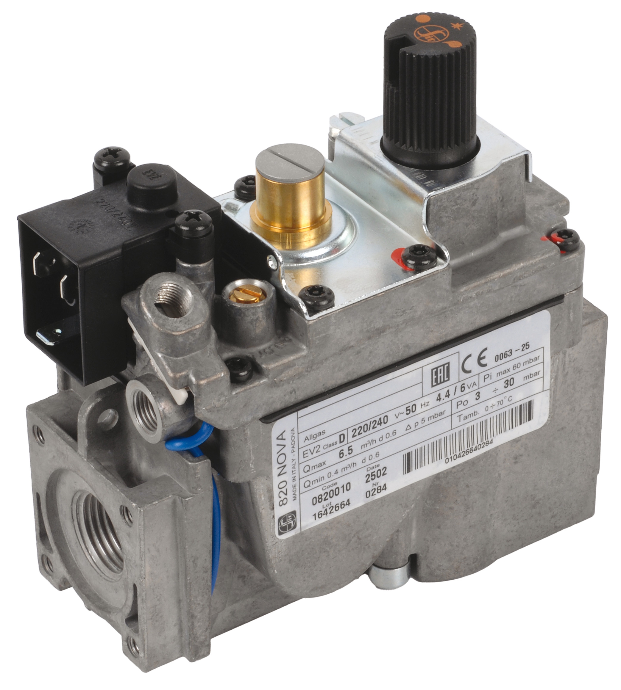
- Mount the gas control block (such as Honeywell VK 4105 C 1041 U for modulating applications) to the burner manifold
- Connect pilot lines and pressure feedback lines with appropriate fittings
- Do NOT pressurize yet; simply verify mechanical integrity
2. Install pressure switches and interlocks – These provide the safety logic foundation
- Mount pressure switches at correct sensing points with isolating ball valves
- Verify sensing lines are free from blockages
- Test manual isolation valves to confirm they operate smoothly
3. Install flame detection components – These must be in place before electrical commissioning
- Position flame sensors per manufacturer specifications (typically 1-2 meters from flame envelope)
- Shield cables from sources of electromagnetic interference
- Route cables through conduit rated for your environment (stainless steel for corrosive areas)
4. Mount and wire the control relay – This is the final major component
- Install the control relay (such as Kramschroder BCU 570WC1F1U0K1-E or Siemens LFL 1.622) in a secure, accessible enclosure
- Wire all safety interlock circuits before connecting main burner circuits
- Use colored wires or labels: Red for 230V supply, Black for safety circuits, Green for ignition circuits
5. Connect the ignition control module – This fires the burner
- Mount the ignition module (such as Pactrol Housing P 16 DI CE) away from heat and vibration sources
- Connect high-voltage ignition leads with appropriate strain relief
- Verify ignition output voltage is isolated from power circuits
Wiring Best Practices for Singapore Industrial Environments
- Use 1.5mm² minimum for safety circuit wiring; 2.5mm² for high-current circuits
- Maintain separation between fuel system and electrical conduit (minimum 100mm)
- Crimp all connections; solder is not acceptable for safety circuits
- Label every terminal at both ends with consistent nomenclature (e.g., "FL1" for flame input)
- Take photographs of completed wiring before testing begins
Section 3: Commissioning Verification and Safety Testing
Commissioning is where you verify the Controls & Safety system functions as designed. This is non-negotiable—burners must not operate until commissioning is complete.
Pre-Ignition Verification (Power Off)
With the main power disconnected:
1. Verify all mechanical components move freely
- Manually cycle the fuel valve (if accessible) to confirm it responds
- Check damper linkages move smoothly through full range
- Confirm pressure gauges read zero
2. Confirm all wiring is secure
- Tug each wire connection to ensure they don't pull free
- Check that no wires are pinched or abraded
- Verify that high-voltage ignition leads are properly shielded
3. Document baseline conditions
- Record all gauge readings with power off
- Photograph the control panel
- Note ambient temperature and humidity
Initial Power-Up (System Startup)
1. Apply power and observe the relay – The control relay should immediately enter a safe state
- Flame signal indicator should be OFF (no flame detected yet)
- Ignition circuit should be READY but NOT firing
- Fuel solenoids should be CLOSED
- If any of these conditions are wrong, power down immediately
2. Test all safety interlocks before attempting ignition
- Verify that breaking any interlock circuit immediately stops ignition attempts
- Confirm fuel pressure switch prevents fuel valve opening if pressure is low
- Check that loss of air damper signal stops the burner
3. Monitor for 10 seconds with no fuel connected – The system should remain in standby
- Listen for any abnormal relay chattering
- Observe for any flickering indicator lights
- Watch for unexpected solenoid activation
Flame Detection Commissioning
Once basic systems are verified:
1. Manually light the burner (with fuel connected) and observe flame detection
- The flame indicator should illuminate within 2-3 seconds of visible flame
- If flame detection is delayed, adjust sensor positioning or check for dirt/dust
- Record the time required for flame recognition
2. Test flame loss response
- With burner operating, briefly block the flame (use a metal plate, not your hand)
- The system should shut down fuel within 2 seconds
- Ignition should not re-attempt unless reset by operator
3. Verify flame signal stability
- Observe the flame indicator for 5 minutes during stable operation
- There should be NO flickering; indicator should be steadily ON
- Any flickering suggests sensor contamination or misalignment
Load Testing and Performance Verification
1. Run the burner at full load for 30 minutes
- Monitor all gauge readings against design specifications
- Check that pressure switches remain in correct state during operation
- Verify that control relay doesn't reset or cycle unexpectedly
2. Test modulation (if applicable)
- Confirm that gas control modulates smoothly across the full range
- Verify that burner doesn't flame out at minimum load
- Check that maximum fuel pressure doesn't exceed design limits
3. Perform emergency shutdown test
- Activate the manual shutdown with burner running
- Fuel should cut off within 1 second
- Confirm safe shutdown without afterburn or delayed cutoff
Create Your Commissioning Report
Document:
- Date, time, and technician name
- All gauge readings at startup, during operation, and at shutdown
- Pass/fail status for each safety test
- Flame detection response times
- Any deviations from design specifications
- Signature of responsible technician
Keep this report with your equipment documentation for future reference.
Section 4: Daily Operational Checks and Ongoing Maintenance
After successful commissioning, your maintenance team must perform regular checks to ensure Controls & Safety reliability.
Daily Operational Checklist (Before Starting the Burner)
- Verify all gauge needles are at zero (power off)
- Check that indicator lamps illuminate when power is applied (control relay alive)
- Confirm no visible damage to fuel lines or electrical conduit
- Inspect the burner area for debris that could block air or obstruct flame sensors
- Review the commissioning report to confirm normal readings
- Monitor flame indicator—should remain steadily lit (not flickering)
- Check pressure gauges every 15 minutes—readings should remain stable
- Listen for any unusual relay clicking or solenoid chattering
- Observe flame color—should be blue (gas) or orange (oil), not yellow or smoky
- Record all gauge readings in a maintenance log
1. Manually activate emergency shutdown – System should cut fuel immediately
2. Verify flame loss response – Block flame briefly; system should shut down
3. Check pressure switch operation – Manually isolate fuel pressure; relay should prevent ignition
4. Inspect flame sensor – Look for soot accumulation or physical damage
Monthly Detailed Inspection
- Clean flame sensor with dry cloth (do not use solvents)
- Check all electrical connections for corrosion or looseness
- Inspect fuel lines for leaks or damage
- Verify that all labeling remains legible and accurate
- Test full emergency shutdown sequence from all control points
Engage qualified service personnel to:
- Perform detailed electrical testing on control relay
- Calibrate pressure switches (critical for SIL 3 rated systems like Kromschroder DG 50U/6)
- Inspect and clean the burner interior
- Review all maintenance logs for trends or repeated issues
- Update your commissioning documentation with current readings
Conclusion
Proper installation, commissioning, and ongoing operational checks are not bureaucratic overhead—they are the foundation of safe, reliable burner operation. Maintenance teams that follow these procedures prevent accidents, minimize downtime, and extend equipment life.
3G Electric has supported Singapore's industrial maintenance teams for over 35 years by providing reliable equipment and practical guidance. When you're ready to install or upgrade your burner control systems, we're here to help with the products and support your team needs.
The time invested in thorough commissioning saves far more time in future emergencies avoided. Make it your standard practice.