Understanding Controls & Safety Emergency Shutdown Architecture
Controls & Safety systems in industrial HVAC applications must incorporate failsafe emergency shutdown mechanisms that respond instantaneously to combustion faults, fuel pressure anomalies, or operator intervention. Unlike standard shutdown sequences, emergency shutdown architecture requires multiple redundant pathways to completely cut fuel supply and halt ignition attempts within milliseconds.
With over 35 years of experience distributing industrial equipment globally, 3G Electric has witnessed how inadequate failsafe design leads to catastrophic equipment damage, personnel injury, and regulatory violations. Emergency shutdown architecture differs fundamentally from normal operational controls—it must function independently of electrical power loss, microprocessor failure, or communication bus collapse.
The core principle underlying failsafe Controls & Safety design is that any single component failure must result in safe shutdown, not continued operation. This "fail-to-safe" philosophy requires understanding how solenoid valves, relay modules, ignition systems, and flame detection circuits interact during emergency conditions. HVAC contractors operating across multiple jurisdictions must recognize that emergency shutdown requirements vary by region—European installations follow EN 60204-1 standards, while North American systems reference NFPA standards and CSA certifications.
Critical Safety Interlocks and Redundant Pathways
Effective Controls & Safety emergency shutdown architecture incorporates multiple independent interlocks that can independently command fuel cutoff. These include flame detection failure interlocks, pressure switch anomalies, temperature overrun conditions, and manual emergency stop circuits.
Flame Detection as Primary Safety Interlock
Flame detection serves as the critical safety interlock preventing unburned fuel accumulation. The Satronic Relay TF 836.3 integrates 2-5 second postignition monitoring that immediately cuts fuel if flame is not established. This relay's 10-second safety response time ensures that if flame is lost during operation, fuel supply terminates before dangerous fuel vapors accumulate in the combustion chamber. HVAC contractors must verify that flame detection circuits operate on independent power supplies separate from main control circuits.
Fuel Shut-Off Valve Redundancy
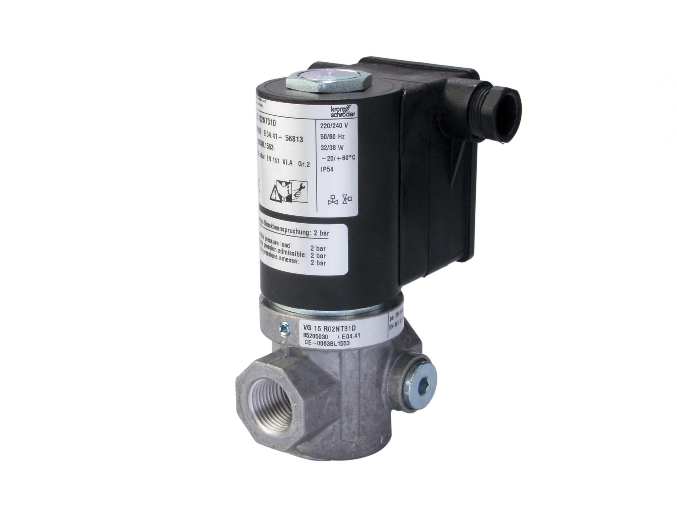
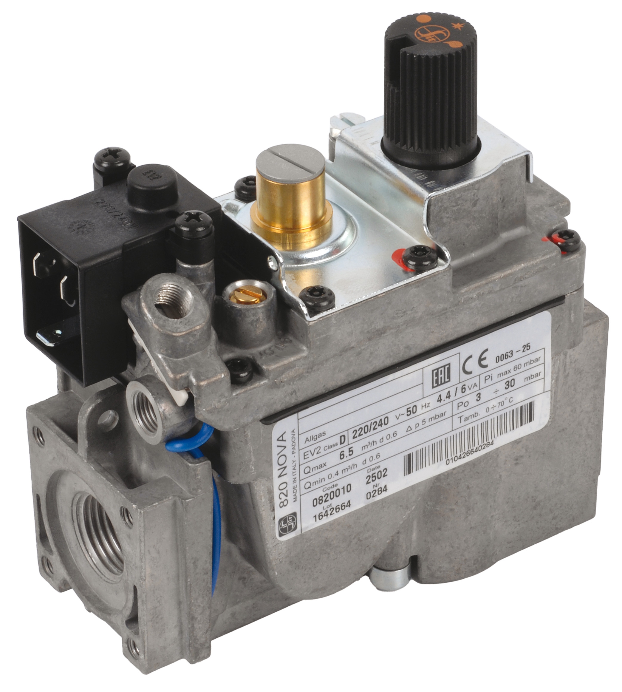
Gas block controls must incorporate dual shutoff pathways. The SIT Gas block Nova 0820010 provides Class D flow ratings suitable for 24 VAC operation with integral pressure switching, but emergency shutdown requires a secondary solenoid valve that functions even if the primary gas block becomes stuck open. The Kromschroder Fast gas solenoid valve VAS 225R/NW with 500 mbar upstream pressure rating and integrated flow adjustment enables rapid fuel cutoff when emergency shutdown signals activate.
Dual solenoid valve architecture means both valves must fail open simultaneously to create an uncontrolled fuel condition—a statistically improbable scenario. The fast response time of Kromschroder solenoid valves (typically 200-300 milliseconds) ensures that fuel supply terminates before ignition can occur if flame is lost.
Pressure Switch Integration
Pressure switches monitoring fuel line pressure serve as secondary interlocks preventing fuel delivery if atomizing pressure, gas supply pressure, or combustion air pressure falls outside safe operating ranges. These switches must interrupt ignition circuits immediately—not gradually reduce firing rate. HVAC contractors should specify pressure switches rated for the exact fuel type and pressure range of their application, with manual reset features for certain dangerous conditions.
Manual Emergency Stop Circuit Design
Emergency stop (E-stop) buttons must command fuel shutoff through a hardwired circuit independent of programmable logic controllers or soft-wired control systems. The E-stop circuit should de-energize fuel solenoids directly, bypass all logic processing, and prevent system restart until intentionally reset by trained personnel. This direct hardwired pathway ensures emergency response even if control system processors fail or lose electrical power.
Burner Control Module Selection for Failsafe Operation
Burner control modules integrate multiple safety functions into unified packages, but HVAC contractors must understand which failsafe features each module provides.
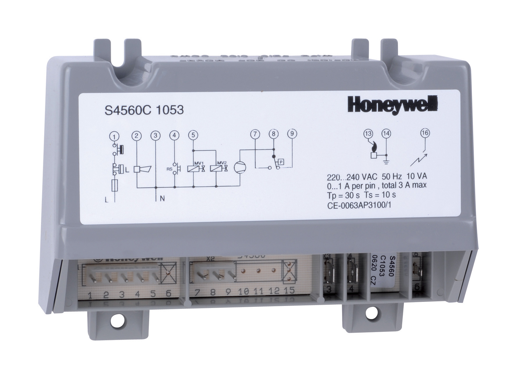
Honeywell S4560 C 1053 U Safety Architecture
The Honeywell Housing S4560 C 1053 U operates at 220-240 V, 50 Hz with adjustable prepurge and waiting times that prevent fuel introduction until combustion air has purged explosive vapor from the combustion chamber. The prepurge cycle typically requires 10-24 seconds of forced air circulation before solenoid valves open, preventing vapor explosions on ignition.
Critically, this module automatically terminates ignition attempts if no flame is detected within the ignition time window (typically 4-6 seconds). If flame is not established, the module closes fuel valves and requires manual reset before attempting reignition. This prevents endless ignition cycles that would accumulate unburned fuel.
Pactrol CSS01 12 Housing Integration
The Pactrol CSS01 12 housing ref 404700 designed for atmospheric and small forced-air burners up to 60 kW integrates timed relay, flame relay, and electronic spark generator functions. The integrated flame relay directly monitors flame rod current, de-energizing fuel solenoids instantly if flame is lost during operation.
For HVAC contractors specifying this module, the critical advantage is consolidated safety logic—fewer external wiring connections reduce failure points where safety interlocks might be inadvertently defeated. The electronic spark generator responds to flame relay commands, enabling synchronized ignition and fuel introduction that prevents fuel introduction before ignition is ready.
Field Implementation and Testing Protocols
Failsafe Controls & Safety architecture requires rigorous field commissioning and regular testing to ensure all safety pathways function correctly.
Pre-Operational Commissioning
Before burner startup, HVAC contractors must verify:
- Fuel valve response: Manually command solenoid valves to open and close, measuring voltage at valve coils and listening for audible click confirming mechanical response. Valves should open within 500 milliseconds and close within 1000 milliseconds.
- Pressure switch calibration: Simulate fuel pressure conditions using pressure simulation gauges, confirming that pressure switches interrupt electrical circuits at specified setpoints.
- Flame detection sensitivity: With burner off, verify that flame rod circuits show high resistance (typically >1 MΩ). After ignition, flame rod current should drop to 2-5 microamps minimum, confirming adequate flame ionization.
- Emergency stop functionality: Activate E-stop button with burner running at full load, confirming immediate fuel shutoff and audible/visual alarms.
- Ignition timing: Measure time from solenoid valve opening to flame establishment using calibrated thermocouple or visual observation. This should occur within 2-3 seconds; longer ignition times indicate fuel supply or ignition system problems.
Annual Safety System Testing
Regulatory standards in most jurisdictions require annual testing of emergency shutdown pathways. HVAC contractors should schedule:
- Flame loss response: With burner operating at full load, interrupt flame detection (block flame rod or simulate zero flame current) and measure fuel shutoff response time. Complete fuel cutoff should occur within 1-2 seconds.
- Pressure switch response: For each pressure switch in the system, verify mechanical function by gradually adjusting pressure from safe to unsafe conditions and confirming electrical interruption at setpoint.
- Solenoid valve mechanical function: Annual manual operation of solenoid valves confirms no corrosion or debris prevents proper closing. Measure magnetic force by attempting to hold valves open against spring closure force.
- E-stop circuit continuity: Verify that E-stop button terminals show proper resistance (typically <1 Ω when pressed) and that fuel shutoff occurs within 500 milliseconds of button activation.
- Power supply redundancy: If emergency shutdown circuits use backup power supplies or uninterruptible power supplies (UPS), verify that these systems charge properly and can sustain emergency shutdown sequence for minimum 10 minutes without main AC power.
Documentation and Compliance Records
HTAC contractors must maintain detailed commissioning records and test logs for every Controls & Safety system they install. These records should include:
- Original equipment specifications and pressure/temperature ratings
- Commissioning checklist with date, technician name, and measured values
- Annual test results comparing current measurements to baseline established during commissioning
- Any repairs or component replacements with part numbers and installation dates
- Compliance certifications confirming installation meets applicable standards (EN 60204-1, NFPA 85, CSA B139)
Global Compliance and Regional Variations
HTAC contractors operating internationally must understand that Controls & Safety requirements vary significantly by region. European Union installations require CE marking and compliance with Machinery Directive 2006/42/EC, which mandates independent emergency stop circuits and automatic shutdown on sensor failure. North American installations reference NFPA 85 (Boiler and Combustion Systems Hazards Code) and CSA B139 standards, which define specific response times for flame loss detection and require demonstrated failsafe operation.
Middle Eastern and Asian installations may incorporate additional safety features for extreme temperature operations, including temperature-based fuel shutoff if combustion chamber temperature exceeds maximum ratings. Australian and New Zealand facilities follow AS/NZS 3992 standards requiring demonstration that all single component failures result in safe shutdown.
When 3G Electric supplies components to contractors across these regions, we ensure that provided documentation includes compliance certifications for target jurisdictions. Contractors should request compliance documentation for specific regions where equipment will operate and confirm that component certifications align with local regulatory requirements.
Troubleshooting and Common Failsafe Failures
When Controls & Safety systems fail to shutdown properly, systematic troubleshooting identifies whether failures originate in detection circuits, control logic, or fuel shutoff hardware.
Delayed Emergency Shutdown Response
If burners continue firing for 3+ seconds after emergency shutdown signal, suspect fuel valve sluggish response. Measure solenoid valve coil voltage—should be within ±10% of nameplate rating. If voltage is adequate but valve closes slowly, internal corrosion or debris may be present. Request replacement solenoid valve and verify fuel quality (water contamination or particulates accelerate valve degradation).
Intermittent Flame Loss Detection
If flame loss detection intermittently fails to trigger shutdown, measure flame rod current during normal operation—should be 2-5 microamps minimum. Lower values indicate weak flame or misaligned flame rod. Clean flame rod electrode with soft wire brush and verify proper positioning (typically 6-12 mm from flame envelope). If flame rod current remains <2 microamps, upgrade burner ignition energy or adjust fuel/air ratio to strengthen flame ionization.
Pressure Switch Nuisance Trips
If pressure switches activate emergency shutdown during normal operation despite adequate fuel pressure, verify switch setpoints using pressure simulation equipment. Pressure switches drift over time; if setpoint is now lower than during commissioning, request replacement. Also verify fuel line contains no pulsations that might cause pressure oscillation around switch setpoint—add damping tank if pulsations exceed ±5% of mean pressure.
E-stop Button Failure to Function
If E-stop button fails to trigger fuel shutoff, first verify electrical continuity through button contacts using multimeter. If button contacts have >5 Ω resistance, clean button terminals or request button replacement. If button continuity is good but fuel shutoff doesn't occur, trace wiring to fuel solenoid and measure voltage during E-stop activation—should drop to zero within 100 milliseconds. If voltage doesn't drop, suspect control relay failure or wiring break in E-stop circuit.
Preventive Maintenance for Sustained Failsafe Performance
Controls & Safety systems require quarterly inspection and lubrication to maintain failsafe function throughout equipment lifecycle. HVAC contractors should:
- Quarterly inspection: Visually inspect solenoid valve coils for corrosion, check flame rod for carbon deposits, and verify all electrical connectors are clean and properly seated.
- Semi-annual pressure testing: Verify that pressure switches still respond at correct setpoints and that fuel line pressures remain stable during full-load operation.
- Annual component replacement: Solenoid valve seals degrade over 12-24 months of operation; proactive replacement prevents fuel leakage that could bypass emergency shutoff. Similarly, flame rod carbon buildup increases over time; annual cleaning or replacement maintains flame detection sensitivity.
- Biennial control module evaluation: Inspect burner control module for signs of thermal stress, corrosion, or loose connections. If any components show degradation, request module replacement rather than attempting repairs, which could introduce latent failures.
3G Electric's 35+ years of experience has demonstrated that contractors who implement rigorous preventive maintenance protocols experience 85% fewer emergency shutdowns due to component failure, compared to contractors who perform only corrective maintenance. Preventive maintenance costs 40-60% less than emergency service calls and equipment replacement following failsafe system failure.