Understanding Integrated Control Module Architecture
Controls & Safety in modern industrial burner systems depend critically on the selection and proper commissioning of integrated control modules. Unlike standalone relay systems, contemporary control modules consolidate multiple functions—flame detection, ignition sequencing, safety shutdown, and postignition timing—into a single compact unit. For plant managers in Singapore, understanding this architecture is essential for minimizing downtime and meeting strict safety compliance requirements.
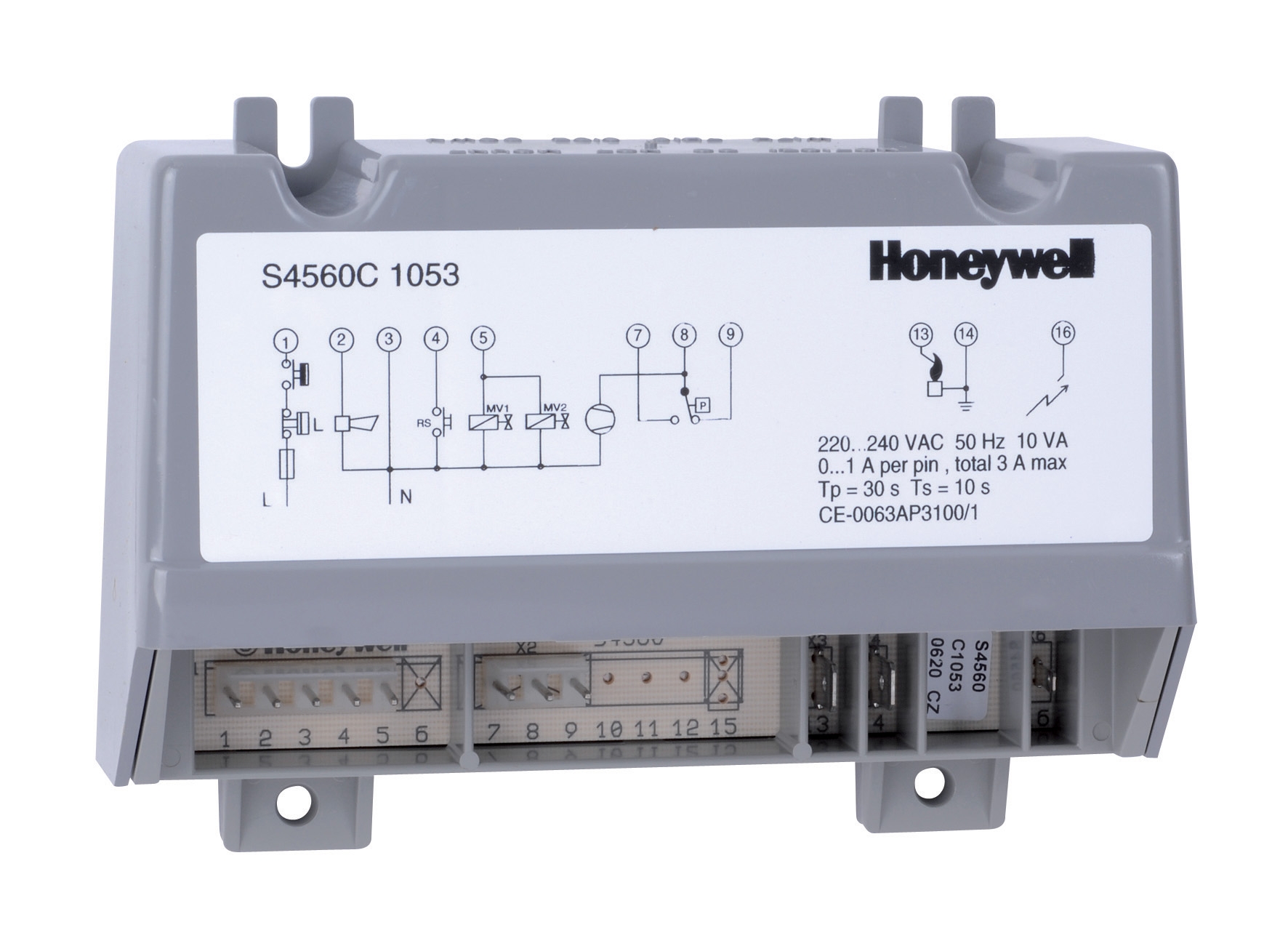
Integrated control modules such as Pactrol CSS01 12 housing and Honeywell S4560 C 1053 U exemplify this consolidated approach. The Pactrol module combines timed relay, flame relay, and electronic spark generator functions in a single housing, reducing wiring complexity and potential failure points. The Honeywell unit operates at 220–240 V, 50 Hz (standard for Singapore industrial facilities) with adjustable prepurge and waiting times of 0–24 seconds each—critical parameters for efficient cold-start sequences and safety compliance.
With over 35 years of experience as a distributor of industrial equipment, 3G Electric has supported hundreds of plant commissioning projects across Southeast Asia. The integration of control modules with other safety components—gas blocks, solenoid valves, and relay systems—requires systematic verification at multiple stages. Premature module failure or unsafe operation typically stems not from component defects but from inadequate commissioning protocols.
Pre-Commissioning Verification and Component Compatibility
Before energizing any control module, plant maintenance teams must verify compatibility across the entire control loop. This involves three distinct phases: documentation review, electrical continuity testing, and functional simulation.
Documentation and Specification Alignment
Start by cross-referencing the control module nameplate against your burner manufacturer's specification sheet. For the Honeywell S4560 C 1053 U, confirm that your 50 Hz supply voltage (standard in Singapore) matches the 220–240 V rating. Check the maximum output current rating—typically 1.3 A at 220 V—against the combined load of all connected safety devices, including the gas block solenoid and spark electrodes. The Pactrol CSS01 12 is rated for burners up to 60 kW; verify your installation does not exceed this capacity.
Next, obtain the manufacturer's control sequence diagram (typically supplied in the module manual). This diagram specifies the sequence of operations: purge time, ignition delay, flame detection window, postignition time, and lockout conditions. The Honeywell S4560 allows independent adjustment of prepurge (0–24 s) and waiting time (0–24 s), enabling you to optimize ignition safety for your specific fuel type and burner air/fuel mixing characteristics.
Electrical Continuity and Grounding
Before powering the module, perform systematic continuity testing across all terminal connections. Use a calibrated multimeter set to resistance (Ω) mode. Test continuity between:
- Terminal blocks and external connectors
- Flame detector input terminals (should show appropriate impedance for your detector type)
- Solenoid valve control contacts (typically NO/NC [normally open/normally closed] pairs)
- Safety interlock input lines (door switch, pressure cutoff)
Grounding is non-negotiable. Measure resistance between the module metal chassis and the facility ground bus. Acceptable values typically range from 0.1 to 1 Ω. Poor grounding introduces electrical noise, which can cause false flame detection shutdowns or delayed response times. In Singapore's tropical climate with high humidity, corrosion of ground connections accelerates; inspect and clean contact surfaces annually.
Functional Simulation Testing
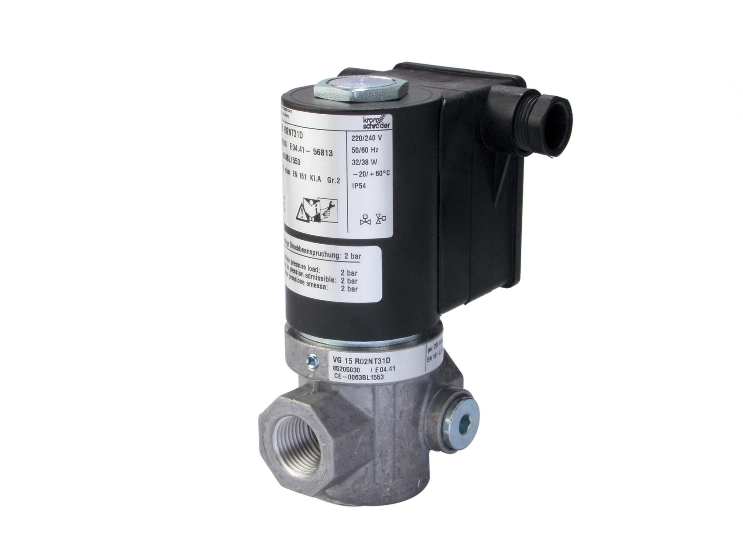
With continuity confirmed, energize the module under no-load conditions and observe LED indicators. The Kromschroder VAS 225R/NW solenoid valve includes a blue LED indicator for status verification. Simulate flame detection by applying a brief signal to the flame detector input (consult the module manual for correct signal voltage—typically 0–5 V DC or resistance-based detection). The module should:
1. Energize the solenoid valve (audible click)
2. Hold the valve open during the flame signal
3. De-energize the valve within 2–5 seconds of losing flame signal (the Satronic TF 836.3 relay, for example, provides 2–5 second postignition safety time)
Record the timing of each transition. Deviations from the manufacturer's specification indicate misadjustment or component failure.
On-Site Commissioning and Parameter Tuning
With the module functionally verified, proceed to on-site commissioning with the burner system operating under controlled conditions.
Ignition Sequence Optimization
The prepurge phase (air circulation before ignition) prevents explosive gas-air mixtures. For atmospheric burners operating in Singapore's hot, humid environment, set prepurge time conservatively—typically 10–15 seconds for domestic applications, 15–20 seconds for industrial equipment. This flushes accumulated gas vapor from the combustion chamber.
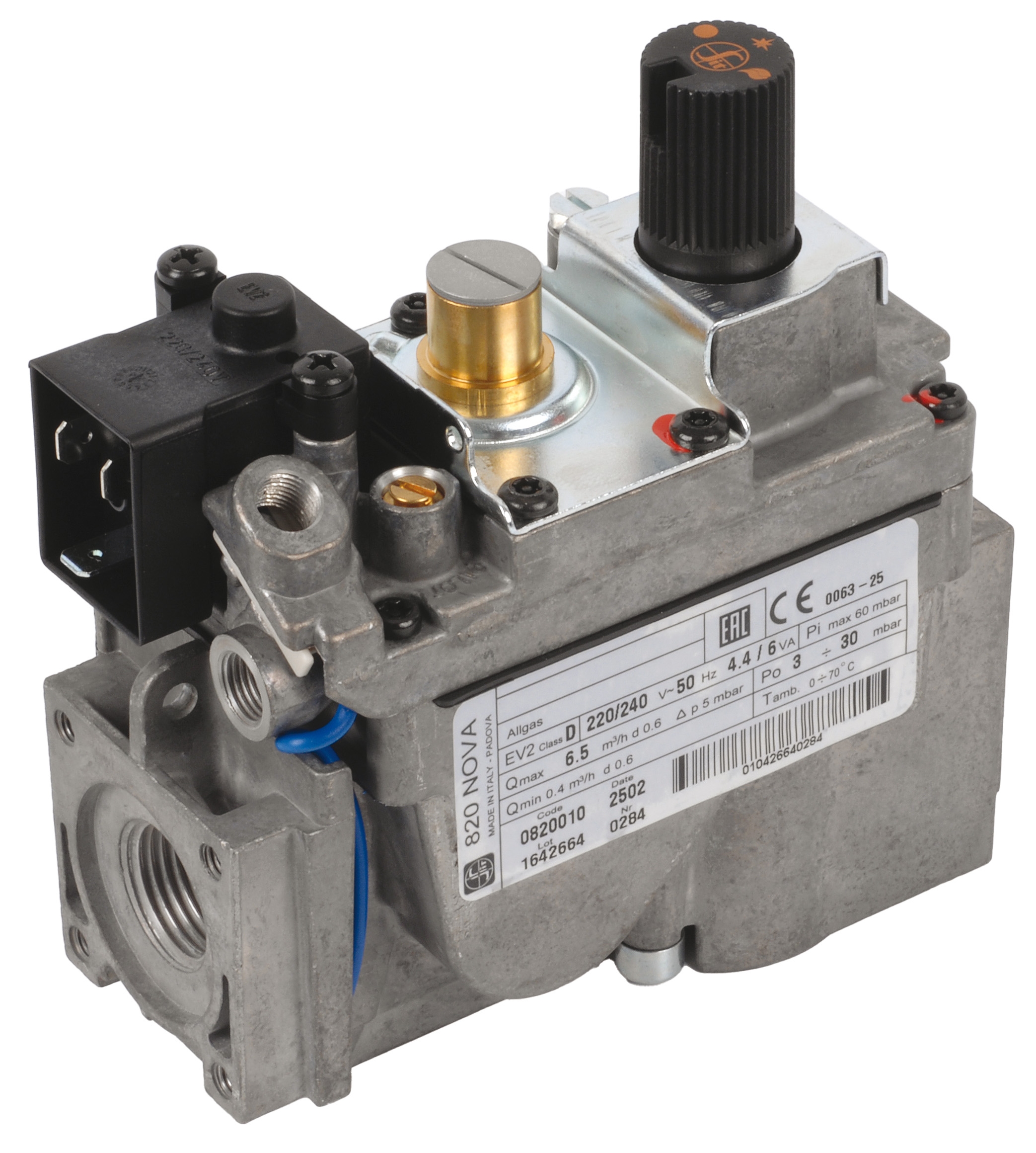
The waiting time (interval between spark electrode energization and burner ignition) compensates for the time required for fuel to reach the combustion zone. For pressure-regulated gas systems using a SIT Gas block Nova 0820010—rated for 5.3–6.5 m³/h depending on gas class—a waiting time of 3–5 seconds is typically adequate. If ignition fails repeatedly, increase waiting time incrementally by 2-second intervals, up to the module's maximum adjustment.
Flame Detection Calibration
Flame detection forms the safety backbone of the control system. After successful ignition, the flame signal must be recognized by the module before the end of the ignition window (typically 5–10 seconds). Measure the flame detector output signal with a DC voltmeter or multimeter set to millivolt mode. For UV/infrared detectors, this signal typically ranges from 0.5 V to 5 V DC depending on flame intensity.
If flame signal is weak or unstable:
- Clean the detector lens with a soft, dry cloth (avoid solvents that degrade optical coatings)
- Verify the detector is not aimed directly at hot metal; angle it 15–30° off-axis to view only the flame itself
- Check that the detector cable is shielded and routed away from high-voltage ignition leads (minimum 100 mm separation recommended)
For systems using Kromschroder VAS 225R/NW with integrated fast-response solenoid valve, the response time is critical. This valve features a 500 mbar maximum upstream pressure rating; verify your gas supply regulator maintains output pressure within this limit, as overpressure can prevent proper valve closure during safety shutdowns.
Safety Interlock Verification
Test all interlock inputs—door switches, low-pressure cutoffs, temperature overrides—individually while the burner is operating at low fire. For each interlock:
1. Trigger the interlock manually (open door, or simulate pressure cutoff)
2. Verify the module shuts down the burner within 2–3 seconds
3. Confirm the module enters lockout mode, requiring manual reset before restart
4. Document the response time for maintenance records
For the Pactrol CSS01 12, interlock response time is directly dependent on the postignition relay delay setting. Conservative commissioning practice sets postignition time at 5 seconds; this provides adequate flame stability verification while maintaining fast safety shutdown capability.
Post-Commissioning Documentation and Maintenance Protocol
After successful commissioning, create a commissioning report documenting all parameter settings, test results, and observed response times. This record becomes the baseline for future maintenance and troubleshooting.
Parameter Lock and Configuration Backup
Many modern control modules allow parameter adjustment via accessible potentiometers or digital interfaces. After commissioning, physically lock or seal these adjustments to prevent unauthorized modification. The Honeywell S4560 uses screw-slot potentiometers; apply a dab of paint across the potentiometer and its mounting bracket as a tamper-evident seal. Photograph this configuration.
Maintain a commissioning checklist specific to your installation:
- Module model, serial number, and software revision
- Prepurge time setting (seconds)
- Waiting time setting (seconds)
- Postignition time setting (seconds)
- Flame detection signal strength (volts DC)
- Interlock response times (seconds) for each input
- Control voltage and supply frequency verification
- Grounding resistance measurement (Ω)
- Date of commissioning and technician signature
Commissioning establishes baseline performance; maintenance ensures it persists. For Singapore's tropical climate, implement quarterly inspection intervals:
- Inspect module housing for corrosion or moisture ingress (open drain holes if present)
- Test all interlock circuits by simulating each fault condition
- Measure flame detector output signal and compare to commissioning baseline (±10% variance is acceptable)
- Clean flame detector lens if signal strength has declined
- Verify solenoid valve click-audible response during test shutdowns
For the Satronic TF 836.3 relay with IP 44 protection, annual external cleaning with compressed air removes dust accumulation. However, do not attempt to open sealed modules unless the manufacturer explicitly permits it.
Root Cause Analysis for Performance Drift
If commissioning parameters drift over time (e.g., longer ignition times, weaker flame signals), systematic diagnosis prevents callbacks. Compare current measurements to the commissioning baseline. Increasing waiting time typically indicates fuel delivery degradation—check the gas block diaphragm for carbon deposits or regulator output pressure drift. Weakening flame signals suggest detector lens fouling, burner fuel nozzle wear, or electronic gain reduction in the amplifier section.
With 35+ years supporting industrial combustion systems, 3G Electric emphasizes that most "module failures" are actually tuning issues resolvable through disciplined commissioning documentation and systematic diagnosis. Proper commissioning and parameter locking prevent the majority of premature control system failures in Singapore industrial plants.