Controls & Safety: From Installation to Operational Validation
Commissioning controls and safety equipment is not simply a box-ticking exercise—it's the critical phase that separates a properly functioning system from one that fails catastrophically when you need it most. With 35+ years of experience distributing industrial equipment globally, 3G Electric has supported thousands of facility engineers and HVAC professionals through the commissioning process. This guide shares the practical validation procedures you need to confirm system integrity before your facility goes live.
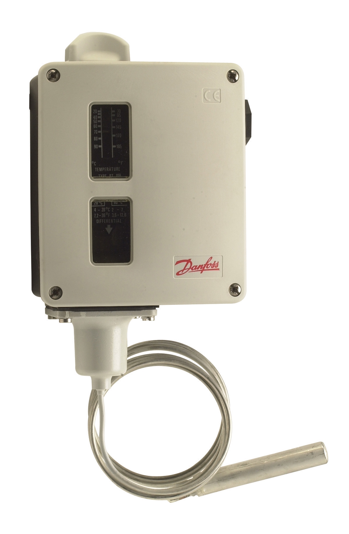
Controls and safety systems protect both personnel and equipment. A thermostat like the Danfoss RT 107 regulates temperature within critical bands, while flame detectors such as the Honeywell Cell C 7044 A 1006 verify combustion in real time. The quality of your commissioning determines whether these devices perform as designed when demand peaks or emergencies occur.
Section 1: Pre-Commissioning System Documentation and Setup
Before energizing any control system, you must establish a baseline understanding of your equipment specifications and system architecture. This foundational work prevents costly rework and ensures you're measuring the right parameters.
Gather Complete Technical Documentation
Collect and organize datasheets, P&ID diagrams, electrical schematics, and manufacturer installation manuals for every component. For thermostat installations using devices like the Danfoss RT 124, you need the exact bulb length, mounting orientation, and differential settings specified by the original design engineer. Discrepancies between your physical installation and documented specifications are red flags that must be resolved before proceeding.
Create a commissioning checklist specific to your system. Include sensor locations, control setpoints, safety interlocks, alarm thresholds, and sequence-of-operation details. This document becomes your reference during testing and your evidence of compliance afterward.
Verify Physical Installation Against Drawings
Walk the system systematically. Confirm that temperature sensors are installed in the locations shown on drawings—not clustered near heat sources or buried in insulation where they won't sense true process conditions. Check that flame detector windows on devices like the Honeywell Cell C 7044 A 1006 are clean, unobstructed, and oriented correctly toward the burner flame. Blocked or misaligned detectors will fail to sense flame during operation, creating a dangerous condition.
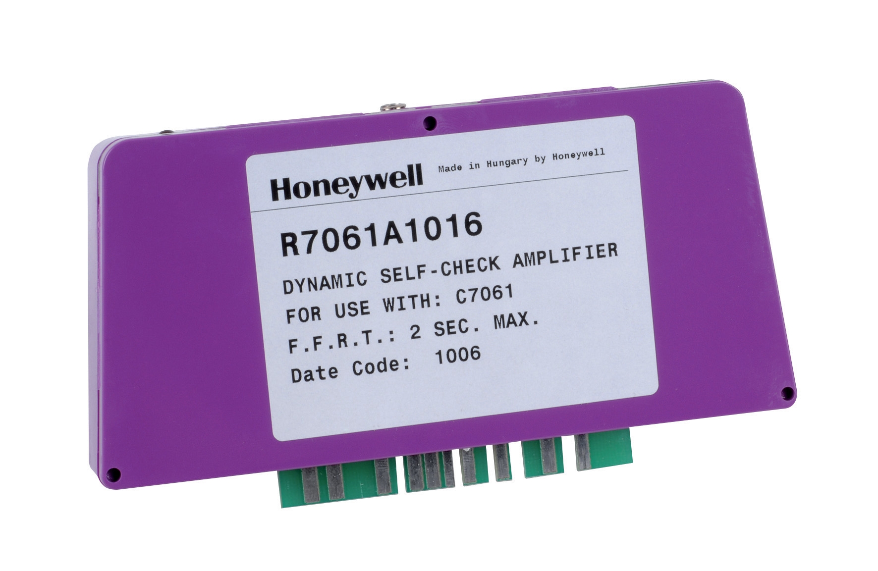
Inspect all wiring for proper gauge, correct termination, and secure connection. Loose terminals on amplifiers such as the Honeywell R7861A 1026 or control modules like the Pactrol CSS01 housing lead to intermittent faults that are nightmare fuel for maintenance teams—faults that appear randomly under load but vanish during troubleshooting.
Verify that mechanical linkages and valve connections match the installation design. A thermostat controlling a heating loop must have its actuator properly sized and mounted to deliver the intended flow modulation.
Section 2: Systematic Testing of Individual Control Components
Component-level testing validates that each device operates within specification before you integrate it into the full system. This modular approach isolates problems early.
Temperature Sensor and Thermostat Validation
Temperature sensors require calibration verification before and after installation. Use a calibrated reference thermometer or precision bath to confirm that your installed sensor reads accurately across the operating range. For the Danfoss RT 107 or Danfoss RT 124, place the bulb in a constant-temperature environment (ice bath, calibration bath, or controlled oven) and verify that the thermostat contact switches at the setpoint temperature documented in your commissioning plan.
Record actual setpoint temperatures, not assumed values. Many facilities discover during commissioning that a thermostat's setpoint dial was misread during installation—a 5°C error can mean inadequate heating or unnecessary energy waste.
Test the thermostat's changeover contact under actual load. At minimum, this means verifying electrical continuity with a multimeter. Better practice is to energize the control circuit and observe the pilot light or valve position change when temperature rises above and falls below the setpoint. This confirms the mechanical and electrical function together.
Flame Detection System Testing
Flame detectors are safety-critical and demand rigorous testing. The Honeywell Cell C 7044 A 1006 and its amplifier require joint commissioning because the amplifier's Honeywell R7861A 1026 sensitivity settings directly affect detector response.
With the burner OFF, confirm that the flame relay (the safety output) is in a de-energized "safe" state. Power loss, detector failure, or insufficient flame signal should all result in the same safe condition: no fuel delivery.
With the burner operating at stable flame, measure the DC signal voltage at the flame detector amplifier terminals. This voltage should be stable and within the manufacturer's specified range (typically 3–8 V DC for a properly burning flame). Unstable or low voltage indicates detector fouling, misalignment, or amplifier malfunction.
Perform a "flame loss" test by briefly blocking the burner flame while observing the flame relay. The relay should drop (de-energize) within 1–3 seconds and remain de-energized until flame is restored and stabilizes. Slow response or failure to de-energize on flame loss is unacceptable and must be corrected before normal operation.
Document the stable signal voltage and relay response time for future reference. If a flame detector later shows erratic behavior, you'll have a baseline to compare against.
Burner Control Module Integration
Control modules like the Pactrol CSS01 integrate timed relays, flame relays, and ignition functions. Test each function independently:
- Ignition sequence: Energize the spark generator and observe spark at the ignition electrode. Weak or absent spark indicates fouled electrodes or insufficient supply voltage.
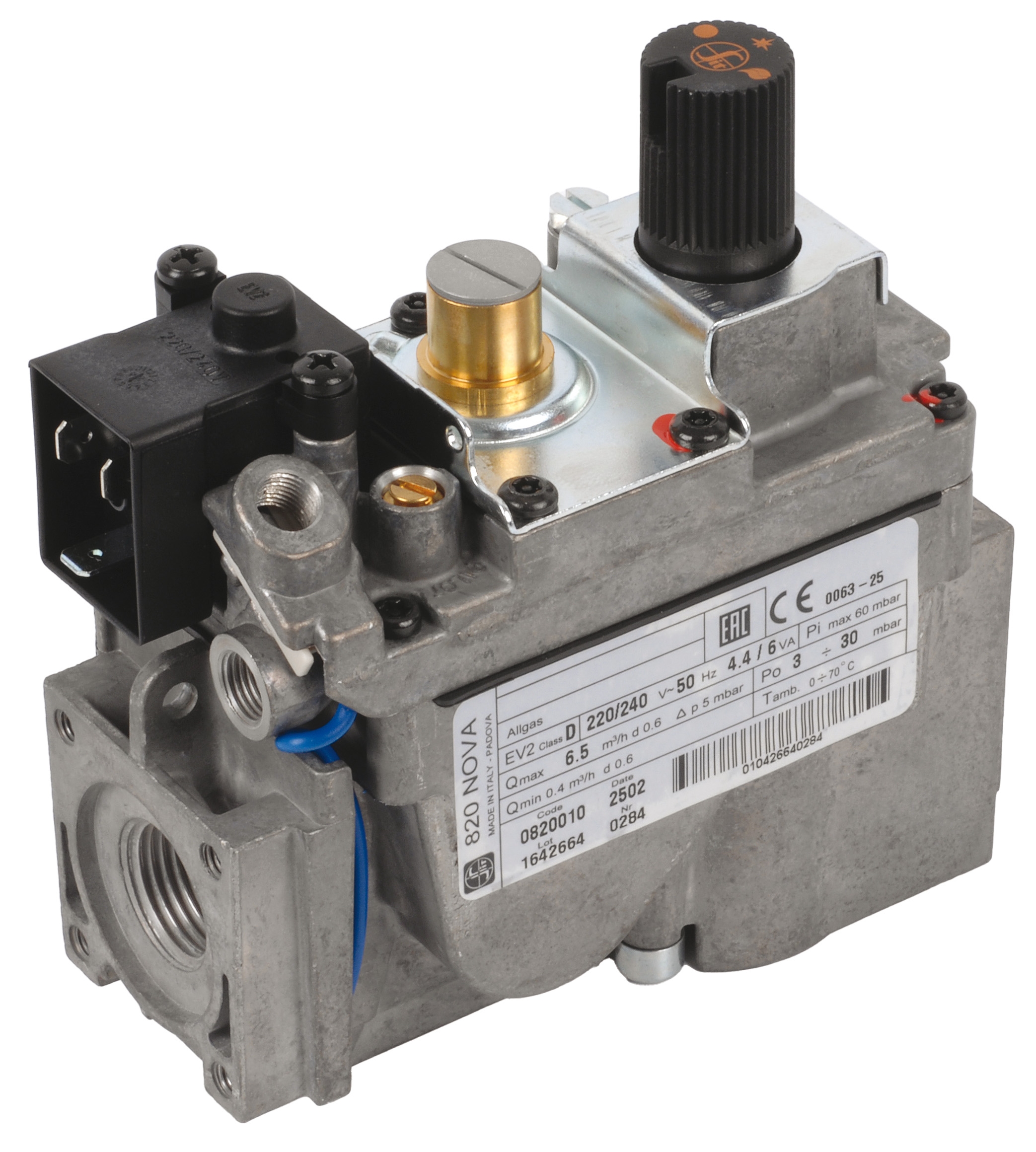
- Fuel valve operation: Confirm that fuel solenoid valves open when the control module energizes them and close when de-energized. Listen for audible clicks and feel for vibration—these are signs of proper electrical activation.
- Sequence timing: The module should delay fuel delivery until spark is confirmed and stable. Verify that fuel does not flow before flame is present.
- Lockout protection: If ignition fails to produce flame within the programmed time (typically 3–5 seconds), the module should shut off fuel and lock out, requiring manual reset. Do not bypass or extend this safety function.
Section 3: System Integration and Full-Cycle Operational Testing
Once individual components pass testing, you must validate the complete system operating through its normal and fault conditions.
Cold-Start Sequence Validation
From a shutdown state (no heat, no flame, all safety interlocks armed), command the system to ignition and allow it to complete a full startup cycle. Observe and record:
1. Pre-purge delay (if equipped): Burner fan runs without fuel to clear combustion chamber.
2. Spark ignition: Spark electrode fires and produces visible spark.
3. Fuel valve opening: Fuel solenoid opens, allowing gas to flow to burner.
4. Flame establishment: Flame appears at burner and stabilizes.
5. Proof of flame: Detector confirms flame, and ignition spark cuts off.
6. Main burner stabilization: Flame burns steadily at the commanded firing rate.
Each step should occur in sequence without hesitation. Delays, restarts, or skipped steps indicate control logic problems or hardware faults that must be resolved.
Run at least three complete cold-start cycles and record timing and flame stability for each. Consistency confirms robust commissioning.
Temperature Control and Load Response
With the system running, command stepwise setpoint changes and observe response. Increase the thermostat setpoint 5°C and confirm that the burner increases firing rate (for modulating burners) or remains at steady flame (for on-off burners) as process temperature rises toward the new setpoint.
Decreasing the setpoint should reduce burner firing rate proportionally. The time from setpoint change to steady-state response should match the thermal mass and design intent of your system—typically 2–10 minutes for industrial heating loops.
Record process temperature, burner firing rate (if measurable), and time to setpoint achievement. Use this data to identify any instability—hunting (oscillating temperature), overshoot beyond acceptable limits, or sluggish response—that suggests tuning or control valve problems.
Safety Interlock and Fault Response Testing
Systematic fault testing confirms that safety systems respond as designed:
- Flame loss simulation: Interrupt flame by blocking the burner aperture or briefly reducing fuel pressure. Confirm that the system shuts off fuel within the response time (typically 1–3 seconds) and does not attempt to reignite automatically.
- Detector fouling: Gently cover the flame detector window (if accessible without stopping the burner) and verify increased signal noise or rapid flame loss response. Clean the detector window and confirm signal stabilization.
- Electrical fault: Momentarily interrupt power to the flame detector amplifier or thermostat and confirm that the system safely de-energizes fuel and cooling systems. Restore power and verify normal restart sequence.
- Manual shutdown: Confirm that any emergency stop button, manual shutoff valve, or isolation switch truly stops fuel delivery and prevents reignition without active reset.
Document each fault test, including the fault introduced, system response, time to safe state, and manual reset procedure (if required).
Section 4: Documentation, Sign-Off, and Handover
Commissioning is not complete until you have created a permanent record of validation that protects both your facility and future maintenance teams.
Create Commissioning Report
Your report should include:
- System description and schematic
- Component model numbers and serial numbers (cross-referenced to purchase records)
- All test procedures performed, with pass/fail results
- Actual measured values (setpoints, response times, signal voltages) with comparison to specification
- Photographs of installed sensors, detectors, and control modules showing location and orientation
- Any deviations from design, with corrective actions taken
- Final sign-off by commissioning technician, facility engineer, and equipment supplier representative
This document is your evidence that the system was validated before operation and provides the baseline for future troubleshooting. If a problem arises months later, comparing current measurements to commissioning data often quickly identifies the root cause.
Operator and Maintenance Training
Before handing over the system to operations, train facility staff on:
- Normal operation: How to command startup, adjust setpoints, and shut down safely
- Alarm and interlock meanings: What alarm conditions mean and how to respond
- Basic troubleshooting: Obvious checks (is fuel turned on?, is power supplied?, are sensors clean?) before calling for service
- Maintenance intervals: When detectors require cleaning, when control modules require testing, when thermostats require recalibration
- Emergency procedures: How to isolate fuel, restart after manual lockout, and contact emergency support
Provide written procedures and reference cards. Staff working night shifts or covering unfamiliar equipment will make better decisions with documentation at hand.
Preventive Maintenance Schedule
Establish a formal PM schedule based on manufacturer recommendations and your facility's operating conditions. For flame detectors and amplifiers, quarterly or semi-annual cleaning and signal verification is typical. Thermostats in stable HVAC applications may need annual verification; thermostats in process heating with wider setpoint swings should be checked semi-annually.
Log every maintenance action, measurement, and part replacement. Over time, this log reveals wear patterns and allows you to predict component life and plan replacements before failures occur.
Practical Takeaways for Your Facility
Systematic commissioning and validation transform controls and safety systems from abstract technical equipment into proven, trusted devices you can rely on. The time and discipline invested during commissioning directly reduce emergency repairs, operator confusion, and safety incidents.
3G Electric's 35 years of industrial equipment distribution have shown us that the facilities with the best safety and reliability records are those where commissioning documentation is thorough, accessible, and actively used by maintenance teams. Start with clear specifications, validate each component methodically, test the complete system under realistic conditions, and document everything. Your future self—and your operations team—will thank you when a sensor needs quick replacement or a mystery alarm appears at midnight.