Understanding Burner Modulation System Architecture
Burners & Combustion equipment operating in Singapore's industrial environment must respond dynamically to varying thermal load demands. Unlike fixed-rate systems, modulated burners adjust fuel flow and air supply in real-time based on feedback from process temperature sensors or steam pressure transducers. The modulation chain consists of five critical components: load demand input, burner control module logic, solenoid valve actuation, air damper positioning, and flame stability feedback.
With over 35 years of experience distributing industrial equipment across Asia-Pacific markets, 3G Electric has observed that 60–70% of modulation-related failures stem not from component defects but from misalignment between sensor calibration, control logic tuning, and actuator response timing. Procurement engineers frequently inherit legacy systems where original commissioning documentation has been lost, making systematic diagnostic procedures essential before authorizing replacement equipment.
Modulation systems operate within three distinct zones: standby (burner off), soft-start ramp (ignition through load pick-up), and steady-state modulation (maintaining setpoint). Each zone has different response characteristics and failure signatures. Understanding these distinctions allows field teams to isolate whether a problem originates in the demand signal, the control algorithm response, or the mechanical/electrical actuator performance.
Diagnostic Procedure 1: Load Demand Signal Verification and Sensor Health Assessment
Step 1: Baseline Signal Documentation
Before troubleshooting modulation lag or hunting (oscillating fuel delivery), establish baseline signal readings under controlled conditions. Use a calibrated multimeter or process control tester to measure:
- Analog demand signal voltage (typically 4–20 mA or 0–10 VDC)
- Signal integrity at the control module input terminals
- Expected versus actual sensor output during a known load change
Common sensor issues include thermocouple drift in high-vibration industrial environments, pressure transducer hysteresis (where readings lag actual process conditions), and corroded terminal connections causing intermittent signal loss. In Singapore's humid coastal industrial zones, connector corrosion is particularly prevalent on equipment located within 5 km of port areas.
Step 2: Simulate Load Transients
Instead of waiting for natural load variations, manually introduce controlled demand changes to observe control system response:
1. Document the time lag between demand signal change and actual fuel valve movement (should be <2 seconds for well-tuned systems)
2. Record the overshoot amplitude—does the burner initially over-supply fuel before settling?
3. Measure the oscillation period if hunting occurs (typically 5–30 second cycles indicate proportional-integral tuning issues)
If response lag exceeds 3 seconds or oscillation persists beyond three cycles, the issue is typically in the control module firmware settings rather than the load sensor itself. Request the original commissioning parameters from the equipment supplier or OEM; modern burner controls allow proportional band, integral time, and derivative time adjustments without hardware replacement.
Step 3: Exclusion Testing for Sensor Validity
Disconnect the demand sensor temporarily and command the control module to a fixed mid-point position (typically 50% fuel delivery). If the system maintains stable combustion at this fixed point:
- The issue is definitely upstream of the burner itself
- Focus diagnostics on the sensor signal path, wiring integrity, and control module calibration
- If combustion becomes unstable at fixed 50% position, the problem may be in flame detection feedback rather than load demand sensing
Diagnostic Procedure 2: Actuator Response and Valve Hysteresis Mapping
Solenoid Valve Performance Under Modulation
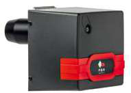
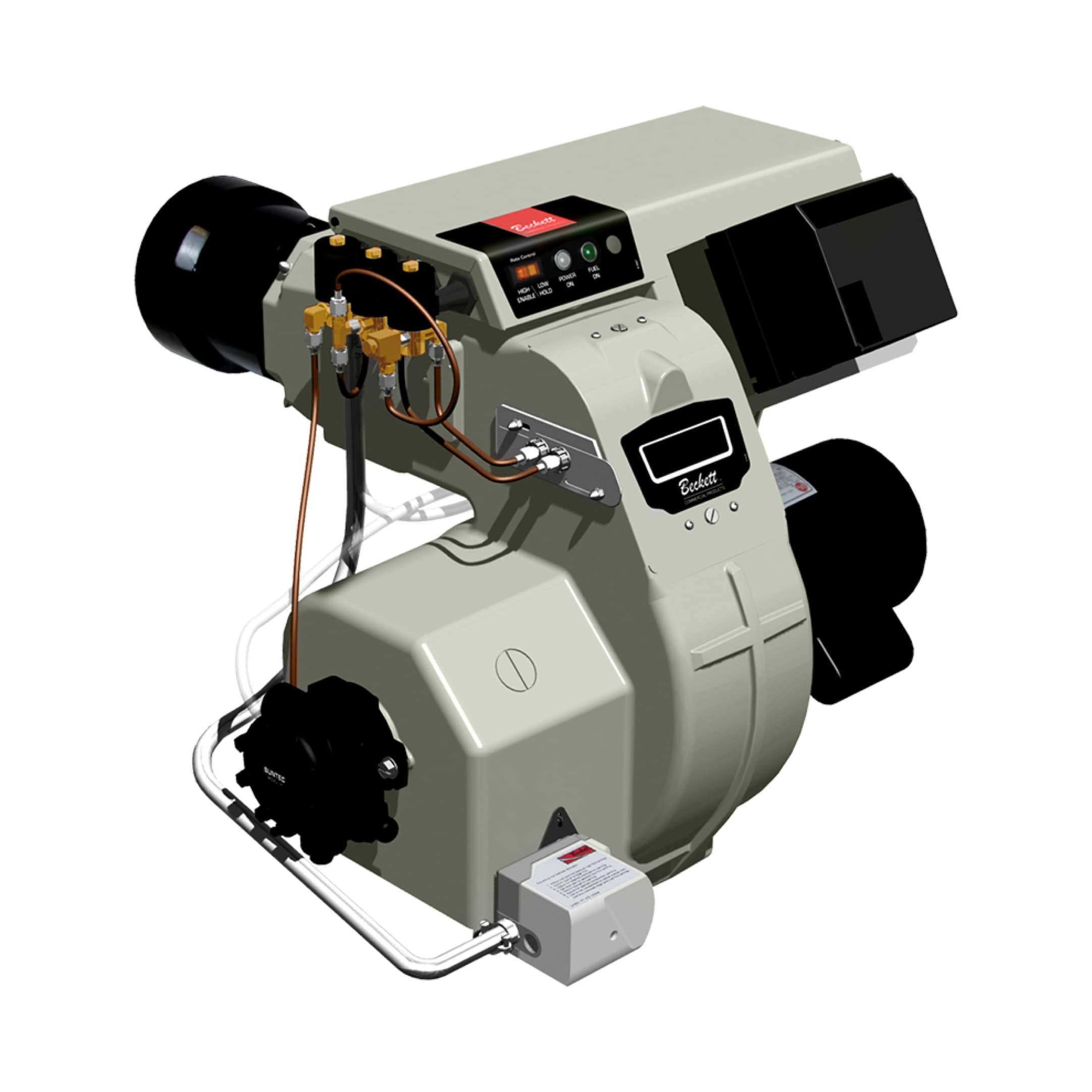
Modulated fuel solenoid valves differ fundamentally from on-off valves; they must respond linearly across their entire stroke range. The Beckett CF3500 Oil Burner and comparable commercial units employ proportional solenoid designs rated for 10,000+ cycle lifespans, but performance degrades when:
- Fuel viscosity drifts outside specification (common in Singapore's tropical storage conditions)
- Internal spool valve wear creates dead-band zones where electrical current changes don't produce fuel flow changes
- Magnetic coil resistance increases due to moisture ingress or thermal cycling
1. Connect an electrical test instrument to the solenoid control signal output (4–20 mA command or 0–10 VDC proportional signal)
2. Slowly increase the control signal from 4 mA to 20 mA in 1 mA increments, recording fuel flow rate at each step
3. Reverse the procedure, decreasing signal from 20 mA to 4 mA, again recording flow rate
4. Plot both curves on a graph; well-functioning valves show nearly identical forward and reverse curves
5. If the reverse curve lags the forward curve by >5% of full flow, the valve exhibits hysteresis and requires replacement
Air Damper Actuator Diagnostics
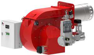
For systems using modulating air dampers (common in gas burners like the FBR Gas Burner with Progressive Modulation), verify that damper position aligns with fuel delivery:
- At 4 mA fuel command, damper should be in minimum air position (typically 20–30% open)
- At 20 mA fuel command, damper should be at maximum air position (typically 80–95% open)
- Response lag between fuel and air changes should be <1 second
If air damper lags fuel delivery, combustion efficiency drops (visible as black smoke during load increase) and flame stability risk increases. If air damper leads fuel delivery, oxygen-rich conditions occur and flame may flare excessively.
Diagnostic Procedure 3: Flame Detection Feedback Loop Validation
Integration of Flame Feedback in Modulation Systems
Modulated burners rely on continuous flame feedback to permit further fuel delivery increases. The Combutech Flame Relay CF1 and UV1p Detection Cell form the detection backbone for many industrial systems. During modulation operation, flame feedback serves two critical functions:
1. Permission signal: Confirms safe combustion before additional fuel is supplied
2. Stability margin: Signals control module if flame intensity is dropping, triggering fuel reduction
UV Detection Cell Signal Quality Assessment
UV detectors with spectral response of 185–260 nm (like the COB02082 unit) are immune to radiant heat but sensitive to electrode wear, soot fouling, and optical port contamination. Under modulation load changes:
- Flame intensity increases 2–3x when modulating from minimum to full fire
- UV cell output voltage should rise proportionally without exceeding relay trip threshold
- Recovery time (typically 20 µS at 10% duty cycle for quality cells) should be fast enough to track combustion changes
Diagnostic steps:
1. Measure UV detector voltage output using an oscilloscope (0–5 VDC typical range)
2. During load increase, observe signal rise time—should reach 80% of final value within 500 mS
3. If signal rise is slower, suspect fouled detector optics; clean or replace the detection cell
4. Monitor signal during 30-minute full-load operation; output voltage should remain stable within ±5%
5. If voltage drifts upward >10%, thermal aging of the UV filter or phosphor coating is reducing sensitivity—replacement is warranted
Relay Response Coordination with Modulation
The flame relay (like the CF1 rated 1 A @ 250 VAC) must not nuisance-trip during normal modulation transients. Coordinate with your control module supplier to verify:
- Flame relay trip threshold is set 20–30% above average steady-state signal level
- Relay has appropriate hysteresis (typically 15–25% dropout margin) to prevent chatter
- Response delay is <200 mS to catch genuine flame-out conditions but slow enough to ignore momentary signal dips during valve switching
Diagnostic Procedure 4: System Integration Testing and Load Cycling Validation
Multi-Point Load Step Testing
After addressing individual subsystem issues, validate the complete modulation chain under realistic operating conditions:
1. Establish stable baseline at 30% fuel demand; document fuel flow rate, combustion CO₂ content, and flame detector signal
2. Step demand to 60% and hold for 5 minutes; observe settling time (<60 seconds for well-tuned systems) and final stability
3. Step demand to 100% and hold for 10 minutes; confirm no overshoot, hunting, or flame instability
4. Cycle demand between 30% and 100% every 2 minutes for 30 minutes; track unplanned shutdowns or limit-switch activations
5. Record any deviation >5% from expected fuel delivery—indicates tuning adjustment or component replacement needed
Efficiency Verification During Modulation
Procurement engineers should mandate efficiency testing under modulated load conditions, not just full-fire operation:
- Measure stack temperature, CO₂ content, and excess air percentage at 30%, 60%, and 100% fuel positions
- For oil burners like the Beckett CF3500, expect combustion efficiency to improve from ~78% at minimum fire to ~88% at full fire
- For gas burners with modulating air (like the FBR HI-GAS P550/M), efficiency should remain within 2–3% across the modulation range
- If efficiency varies >5% across load points, this signals air/fuel ratio drift; adjust burner primary air settings or fuel pressure regulation
Establish a structured log capturing any unplanned burner shutdowns over 30-day test period:
- Timestamp and load condition when shutdown occurred
- Last recorded flame detector voltage immediately before shutdown
- Whether shutdown was due to flame relay trip (safety) or control module derate (non-critical)
- Time required to re-establish ignition
Pattern analysis often reveals whether failures correlate with specific load points (suggesting control tuning issues), time-of-day (indicating thermal cycling or fuel supply temperature effects), or random occurrence (implying intermittent electrical contact or sensor drift).
Common Modulation Failure Modes and Quick Remedies
Hunting/Oscillating Fuel Delivery
Symptom: Fuel flow oscillates 10–20% around setpoint with 10–15 second cycle
Likely cause: Proportional band too narrow; integral time too aggressive
Remedy: Request control module tuning adjustment from OEM; increase proportional band 25–50%, increase integral time constant 2–5 seconds
Slow Response to Load Increase (>3 second lag)
Symptom: When process load increases, burner fuel delivery lags by several seconds
Likely cause: Demand sensor signal poor quality; solenoid valve sluggish; control module response delay setting
Remedy: Test sensor with independent instrument; check solenoid coil resistance; if normal, increase control module response gain by 20–30%
Flame Instability During Modulation (random flicker)
Symptom: Flame detector signal fluctuates; occasional nuisance shutdowns during load transients
Likely cause: UV detector window fouled; flame relay threshold incorrectly set; air/fuel ratio skewed
Remedy: Clean or replace detection cell; verify relay threshold is 20–30% above average signal; check air damper is correctly positioned for fuel flow command
No Response to Demand Signal (burner stays at fixed position)
Symptom: Demand signal changes but burner fuel delivery does not vary
Likely cause: Solenoid valve failure (coil open or spool stuck); control module output circuit failure; feedback potentiometer disconnected
Remedy: Measure solenoid coil resistance (typically 20–80 Ω); if open, replace valve; if normal, test control module output voltage directly at valve terminals; if no voltage, request control module repair/replacement
Procurement Recommendations for Modulation-Prone Environments
When specifying replacement burners or flame detection systems for Singapore industrial sites, 3G Electric recommends:
1. Select proportional solenoid valves rated for minimum 5,000 modulation cycles/year to ensure <2% drift over 5-year service life
2. Specify UV detection cells with integral optical purging (self-cleaning designs reduce maintenance cost in dusty environments)
3. Request control modules with accessible parameter adjustment (field tuning capability reduces dependence on OEM service calls)
4. Mandate comprehensive commissioning documentation including as-found and as-left sensor calibration data, tuning parameters, and baseline efficiency readings
5. Establish preventive UV detector cleaning schedule (monthly in clean environments; bi-weekly in combustion-dust-prone locations)
3G Electric can supply all major modulation system components—flame relays like the CF1, detection cells like the UV1p, complete burner units from Beckett and FBR product lines, and integration technical support. Our 35-year history supporting Southeast Asian industrial operations means we understand regional environmental challenges and can recommend appropriate component selections and maintenance cadences for your specific application.