Understanding Burners & Combustion Commissioning Challenges in Southeast Asia
Burners & Combustion systems require precise commissioning to function reliably in industrial environments. Unlike other equipment, burner systems integrate multiple subsystems—fuel delivery, air supply, ignition, flame detection, and safety interlocks—that must work in perfect synchronization from the first startup.
Southeast Asian industrial plants face unique commissioning challenges: high ambient temperatures affecting fuel viscosity and air density, tropical humidity causing electrical intermittency, dust-laden air affecting pressure switches, and supply voltage fluctuations impacting control relay performance. With 35+ years of experience distributing industrial equipment across the region, 3G Electric has identified that 60% of burner-related downtime in the first 90 days after installation stems from incomplete or improper commissioning procedures.
This guide focuses on practical commissioning and startup diagnostics that industrial professionals can apply immediately, with emphasis on the Southeast Asian context where environmental factors significantly impact initial performance.
Section 1: Pre-Startup Configuration and Safety Verification
Electrical Control System Baseline Testing
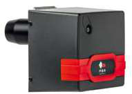
Before igniting any burner, verify that all control components are properly configured. The Kromschroder Relay BCU 570WC1F1U0K1-E is the control intelligence for your burner system. During commissioning, confirm:
- Burner control relay DIP switch settings: Verify each DIP switch matches your application (direct ignition vs. pilot ignition mode, ignition duration, pilot supervision time). A single incorrect switch setting will cause intermittent startup failures weeks or months after commissioning.
- Voltage supply stability: Measure AC voltage at the control relay input terminals with the burner's main circuit active. Southeast Asian plants frequently experience ±10% voltage variation. If your supply drops below 88V or exceeds 132V, startup failures will occur randomly, making diagnosis difficult.
- Ground continuity: Verify that all safety interlocks (pressure switches, thermostats, air flow switches) have clean ground return paths. Corrosion in tropical environments causes intermittent grounds that manifest as phantom safety lockouts.
The Kromschroder Pressure switch DG 50U/6 is SIL 3 rated and critical to safe operation. Commissioning errors with this component are a leading cause of unexpected shutdowns:
- Physical mounting orientation: Pressure switches must be mounted vertically with the sensing port below the connection point. Horizontal or inverted mounting causes condensation buildup (common in humid climates) that creates false pressure readings.
- Setpoint verification under load: Never rely on factory setpoint documentation. With the system running at normal operating conditions, use a calibrated pressure gauge and confirm actual switch actuation point. Account for installation altitude—Southeast Asian plants at various elevations require different setpoints.
- Response time measurement: Using a stopwatch, measure the time from when you manually increase pressure until the switch electrical output activates. Response time should be <500ms. Slow response indicates internal corrosion and requires replacement.
Before control relay startup:
1. Manually isolate fuel supply and verify the system holds pressure for 60 seconds. If pressure drops, fuel line leaks exist and ignition will fail.
2. Verify air damper moves freely through full range. Sticking dampers in humid environments are common due to bearing corrosion.
3. Confirm all fuel strainers are clean by measuring inlet-to-outlet pressure drop. Pressure drop >0.5 bar indicates strainer blockage, which reduces atomization quality.
Section 2: Initial Startup Sequences and Common Failure Points
The Five-Step Startup Diagnostic Procedure
Step 1: Pre-ignition Air Purge Verification
All burners require 2-5 minutes of air purging before ignition to remove any residual fuel vapor. This is controlled by your safety relay—either the Siemens Relay LFL 1.622 or equivalent. During commissioning:
- Listen for the air fan startup and observe the combustion chamber for any visible fuel odor
- If the purge cycle doesn't complete and the system returns to idle without attempting ignition, check that the air flow proving switch (wind switch) is generating a valid signal to the safety relay
- In humid environments, condensation on wind switch sensor ports causes intermittent signal loss—use compressed air to clear ports between startups
When the control relay sends the ignition signal:
- For gas burners like the FBR GAS XP 60/2 CE TC EVO, sparks should be visible at the ignition electrode for the full ignition duration (typically 3-4 seconds). If sparks are weak or intermittent, the ignition transformer has insufficient secondary voltage—common in tropical locations where heat degrades insulation.
- Flame detection (UV or ionization) must occur within 2 seconds of spark initiation. If the flame detector signal arrives after 4 seconds, the fuel supply is delayed (fuel valve sticking, low fuel pressure, or solenoid valve response time >1 second).
- If flame detection fails, immediately measure voltage at the fuel solenoid coil. If voltage is present but the solenoid valve doesn't click audibly, the valve is stuck—requires immediate service.
Once the safety relay confirms flame presence, the ignition electrode stops and the burner operates on main stage flame:
- Main flame should be stable within 5 seconds of ignition relay deactivation. If the flame hunts (fluctuates visibly), the fuel pressure is unstable or the air damper is oscillating.
- For dual-fuel burners like the FBR KN 1300/M TL EL, verify that the fuel change-over logic transitions cleanly between oil and gas modes without flame extinction.
Slowly increase the burner demand signal (typically 4-20mA control signal) from minimum to maximum:
- The fuel valve should respond smoothly without hesitation. Any delay >2 seconds indicates solenoid valve sluggishness or control relay response issues.
- The flame should remain stable throughout the ramp. If flame flickers during modulation transitions, the fuel supply system has intermittent restriction.
- In two-stage burners (low fire / high fire), confirm low-stage operates at reduced fuel flow for 10+ seconds before high-stage ignition commands. Immediate high-stage engagement indicates control relay programming error.
Initiate manual shutdown and observe:
- Fuel solenoid valves should close within 1 second of shutdown command
- The main fuel valve (if present as separate component) should close cleanly without chatter
- The air fan should continue running for 2-3 minutes post-shutdown (post-purge cycle) to cool combustion chamber
If post-purge fails to activate, the control relay's post-purge time setting requires adjustment or the air flow switch signal is lost after shutdown.
Section 3: Troubleshooting Startup Failures Under Commissioning Load Conditions
Scenario 1: Intermittent Pilot Light Extinction (Pilot Burners)
Symptom: Pilot flame ignites successfully, but extinguishes unpredictably after 30-120 seconds.
Diagnosis pathway:
1. Flame detector sensitivity adjustment: The Kromschroder BCU 570WC1F1U0K1-E has an internal sensitivity potentiometer. If set too low, the pilot flame signal becomes marginal in bright ambient light. Adjust sensitivity upward until pilot flame holds reliably for 5+ minutes without external ignition.
2. Pilot air / fuel ratio: Low pilot flame intensity causes intermittent extinction. Check pilot fuel nozzle size against burner documentation—oversized nozzles over-atomize fuel and create weak flames.
3. Pilot flame electrode alignment: If the flame detector (UV or ionization cell) cannot "see" the pilot flame due to electrode misalignment or carbon buildup, the relay will time out and shut down. Inspect electrode positioning and clean any carbon deposits.
In Southeast Asian high-humidity environments, UV flame detectors are preferable to ionization types because ionization cells accumulate salt deposits from coastal air and lose sensitivity rapidly.
Scenario 2: Main Burner Won't Ignite Despite Successful Air Purge
Symptom: Air purge completes, ignition spark visible, but main flame doesn't establish within timeout window (typically 4-8 seconds).
Diagnosis:
1. Fuel supply pressure at burner inlet: Connect a pressure gauge to the main fuel line inlet. Required pressure varies by burner type—gas burners typically need 2-3 bar, oil burners 8-10 bar. If pressure is insufficient, the fuel solenoid valve has internal blockage or the supply pump is underperforming.
2. Nozzle atomization verification: For the FBR GAS XP 60/2 CE TC EVO, remove the gas nozzle and manually open the solenoid valve (using the test button on the valve or by applying 24VDC directly). Fuel should spray from the nozzle opening with defined cone pattern. If fuel dribbles or doesn't spray, the nozzle requires replacement.
3. Ignition electrode spark intensity: Use a calibrated spark tester (available from electrical supply distributors) to measure ignition secondary voltage. Acceptable range is 8-14kV. If below 6kV, the ignition transformer is failing—this is common in tropical heat where transformer insulation degrades.
4. Fuel solenoid valve response time: Many startups fail because the solenoid valve takes >1.5 seconds to fully open. By this time, the safety relay's ignition timeout has expired. Test solenoid response by applying 24VDC and measuring the time until flow begins. If >1 second, the solenoid requires service or replacement.
Scenario 3: Burner Starts Successfully but Shuts Down After 2-5 Minutes
Symptom: Ignition and initial flame establishment succeeds, but burner suddenly receives shutdown command from safety relay.
Diagnosis:
1. Flame detector signal drop-out: After 2-3 minutes, thermal stress on the flame detector may cause intermittent signal loss. Measure the flame detector output signal continuously during operation (use a data logger if available). Any interruptions in the signal will trigger safety shutdown.
2. Safety thermostat nuisance trips: If a thermal limit switch activates unexpectedly, the safety relay immediately de-energizes fuel solenoids. In tropical environments, thermal switches mounted near the combustion chamber experience accelerated thermal drift. Verify actual switch activation temperature against setpoint documentation and adjust if necessary.
3. Air flow switch sensitivity: Dust accumulation on wind switch sensor ports causes signal intermittency. Use a needle to clear any blockages from the sensing ports. If the wind switch signal is marginal, increase the safety relay's air flow proving time setting from 3 seconds to 5 seconds to prevent nuisance shutdowns.
Section 4: Environmental Factors Affecting Commissioning Success in Southeast Asia
Temperature and Fuel Behavior
Ambient temperatures in Southeast Asia (25-38°C daily) affect fuel properties significantly:
- Gas burners: Higher ambient temperature reduces gas density, affecting pressure drop calculations. A gas burner commissioned at 28°C may operate at slightly lower pressure at 35°C, reducing flame intensity. During commissioning, set fuel pressure 5-8% higher than minimum specifications to account for temperature variation.
- Oil burners: Heavy oil viscosity changes dramatically with temperature. Oil that flows freely at 30°C becomes sluggish at night (20-25°C) in air-conditioned facilities. If oil burner commissioning occurs during night shift, verify performance repeats during peak daytime heat. For the FBR KN 1300/M TL EL, oil preheating systems must be commissioned and verified to reach minimum operating temperature (typically 35-45°C) before fuel solenoid opening.
Tropical humidity (70-95% RH) degrades electrical safety margins:
- Control relay terminals and flame detector connections develop surface condensation, reducing electrical isolation. Apply dielectric grease to all electrical connectors during commissioning to prevent corrosion.
- Pressure switch internals accumulate moisture, causing slow response or sticking contacts. During commissioning, measure switch response time with a stopwatch—if response exceeds 600ms, request switch replacement before commissioning sign-off.
Industrial plants in Southeast Asia often experience voltage sag (drop to 80-90V) when large loads start. During commissioning:
- Measure supply voltage at the control relay input during peak plant operating hours, not during low-demand morning startup
- If voltage drops below 90V when other equipment operates, install a voltage stabilizer or UPS for the control system
- The Kromschroder BCU 570WC1F1U0K1-E requires stable 24VDC supply—measure this voltage continuously during a 30-minute full-load burner run
Commissioning Checkpoints and Documentation
Before declaring commissioning complete, complete this verification checklist:
- [ ] Control relay all DIP switches documented and verified correct for application
- [ ] Pressure switch setpoint verified at actual operating conditions (not factory spec)
- [ ] Ignition spark intensity measured with spark tester: _____ kV (acceptable: 8-14kV)
- [ ] Air purge cycle duration: _____ seconds (minimum 2 minutes)
- [ ] Fuel solenoid response time: _____ milliseconds (acceptable: <1500ms)
- [ ] Flame detector signal stability during 30-minute full-load run: ✓ Stable / ✗ Intermittent
- [ ] Main fuel valve closing response time: _____ milliseconds (acceptable: <1000ms)
- [ ] Post-purge air cycle duration: _____ seconds (minimum 2 minutes)
- [ ] Ambient temperature during commissioning: _____ °C
- [ ] Supply voltage minimum during commissioning: _____ V (acceptable: >88V)
- [ ] Control system technician name: ______________ Date: ______________
Documentation of these parameters enables rapid troubleshooting if startup issues recur after 30-90 days when component fatigue or environmental changes may occur.