Burners & Combustion System Integration: Complete Technical Guide for Industrial Procurement Engineers
Burners and combustion systems form the thermal backbone of industrial operations, yet procurement engineers often face fragmented information when sourcing components. This technical explainer bridges that gap, providing actionable insights into system architecture, component compatibility, and integration best practices. With over 35 years of experience as an global industrial equipment distributor, 3G Electric has guided thousands of procurement teams through complex burner and combustion installations across diverse industries—from food processing to chemical manufacturing, power generation, and district heating systems.
Understanding burners and combustion extends beyond selecting a single unit; it requires knowledge of how modulation kits, safety relays, solenoid valves, and flame detection systems work in concert to deliver safe, efficient, and reliable thermal output. This guide equips you with the technical foundation to make informed procurement decisions.
The Complete Burner & Combustion System Architecture
A modern industrial burner system comprises five critical subsystems: the burner unit itself, fuel delivery and regulation, ignition and flame detection, control and modulation, and safety interlocks. Each component must be specified and procured with attention to compatibility standards, regulatory compliance, and operational efficiency targets.
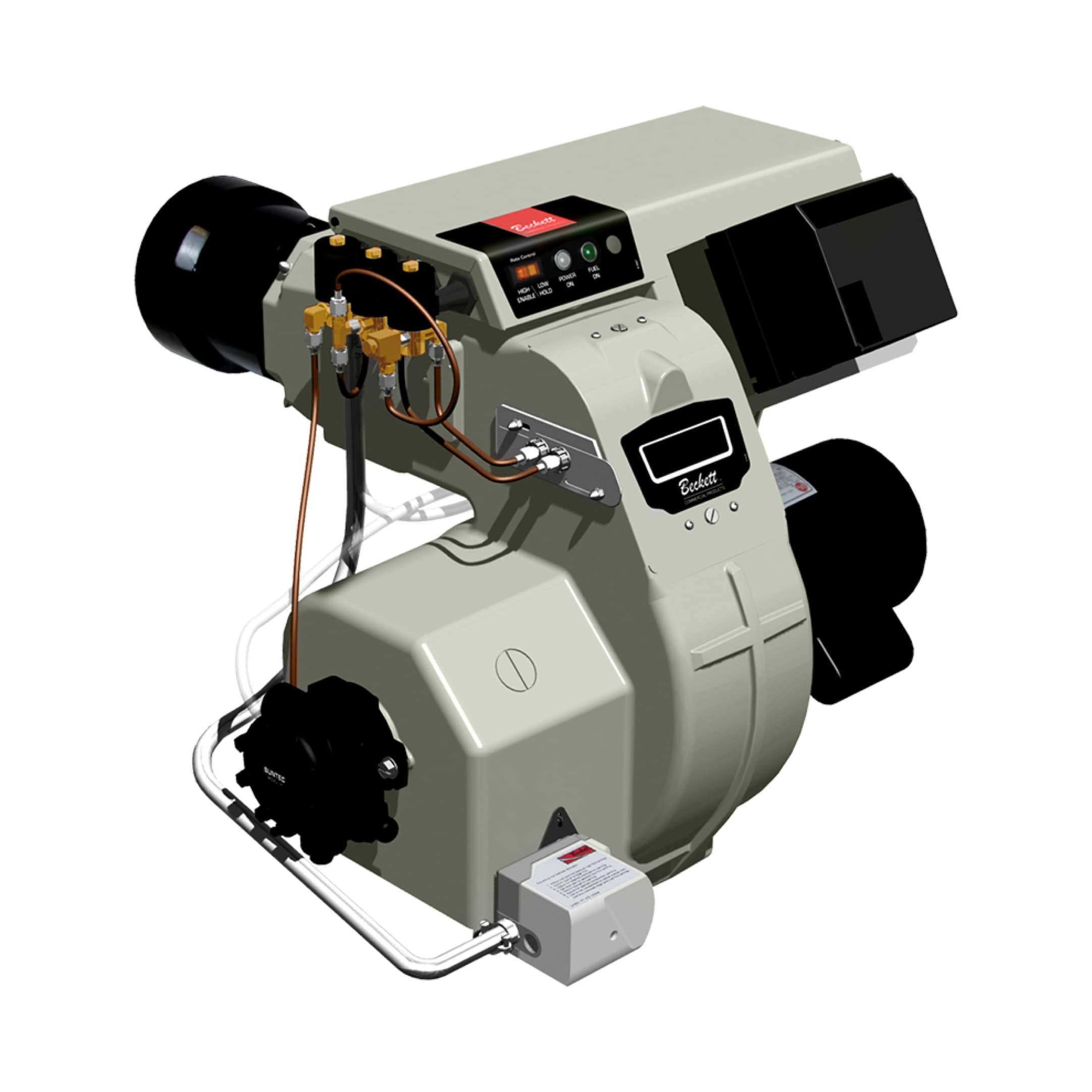
The burner unit—such as the FBR BURNER GAS X5/MF TL EL VC LPG—serves as the primary combustion device, featuring a die-cast aluminum body and high-pressurization fan designed for precise air-fuel mixing. However, this component alone cannot function safely. It requires integration with fuel delivery systems, typically managed through double solenoid valves like the CBM VCS 1E25R/25R05NNWL3/PPPP/PPPP double solenoid valve, which provide redundant safety isolation and proportional flow control.
The control tier incorporates flame detection relays and modulation controllers. The CBM Flame relay CF1 continuously monitors flame presence, providing real-time feedback to the combustion control logic. For advanced applications, the CBM Relay CM391.2 30.5 1.2 handles complex control sequences, while the CBM Base LGK AGM17 provides the electrical mounting interface that ensures standardized integration across different burner configurations.
This layered architecture—burner unit → fuel valve → flame detection → control relay → mounting base—represents industry best practice and ensures that every component can be independently specified, tested, and replaced without redesigning the entire system.
Modulation Capability and Control Strategy Selection
One of the most critical decisions in burner and combustion procurement involves choosing between modulating and on-off control strategies. The FBR BURNER GAS X5/MF series supports full PID (Proportional-Integral-Derivative) modulation when equipped with optional modulation kits and temperature probes, enabling continuous adjustment of burner output to match actual thermal demand.
For procurement engineers, modulation selection depends on three factors: load variability, energy efficiency targets, and capital budget constraints. Modulating burners and combustion systems reduce fuel consumption by 15-25% in applications with variable thermal loads—typical in batch processes, space heating, and seasonal production. However, they require higher initial component costs and more sophisticated control infrastructure.
When specifying modulation capability, ensure that the solenoid valve (such as the CBM VCS series) supports proportional flow rather than simple two-position switching. These valves maintain a linear relationship between control signal (typically 0-10V DC) and gas flow rate, enabling smooth burner modulation. Pair this with a flame relay (CF1) that samples flame signal at appropriate intervals—usually 0.5 to 2 seconds—to maintain stable combustion across the entire modulation range.
Non-modulating systems offer simplicity and lower cost but consume more fuel and generate unnecessary stress on burner components through frequent on-off cycling. This approach is appropriate only for applications with predictable, consistent thermal loads where operational duration is well-defined.
Safety Integration: Flame Detection, Redundancy, and Interlocks
Burner and combustion safety represents a non-negotiable procurement requirement. Industrial safety standards (ISO 13849-1, ASME, CE marking) mandate specific safety architectures that cannot be compromised or substituted. The flame relay—exemplified by the CF1 model—provides the first layer of safety detection by continuously confirming flame presence during burner operation.
The CF1 flame relay typically uses ultraviolet (UV) flame sensing technology, which detects the UV radiation characteristic of hydrocarbon combustion. This method is independent of flame color and fuel type, making it suitable for dual-fuel burners operating on natural gas, LPG, or other gaseous fuels. The relay's response time is typically 3-4 seconds, allowing it to shut down fuel supply if flame is lost during operation.
For enhanced safety in critical applications, procurement engineers should specify double solenoid valve systems. The CBM VCS 1E25R solenoid valve incorporates two independent solenoid coils controlling gas flow through separate seats. This redundant architecture ensures that a single solenoid failure cannot result in uncontrolled fuel delivery. Both solenoids must be energized to maintain fuel flow; loss of either signal immediately halts combustion.
The control relay (CM391.2) extends safety logic beyond simple flame detection. It manages sequence interlocks such as: air pressure confirmation before ignition, lockout timers that prevent rapid re-ignition attempts, and shutdown confirmations that verify solenoid closure. These functions create a safety chain that prevents dangerous scenarios like unburned fuel accumulation or flame loss during operation.
When procuring these safety components, verify their certification status. Flame relays and control relays must carry appropriate certifications—UL (North America), CE (Europe), or equivalent—confirming compliance with applicable safety standards. The mounting base (LGK AGM17) standardizes electrical connections and ensures that control circuits meet voltage and current requirements without field modifications that could compromise safety integrity.
System Compatibility and Component Selection Workflow
Burner and combustion system procurement requires systematic compatibility verification across fuel type, pressure rating, electrical supply, and control signals. The FBR BURNER GAS X5/MF series operates on liquefied petroleum gas (LPG) at specific inlet pressures (typically 1.0-1.3 bar for LPG, varying by nozzle configuration). The corresponding solenoid valve must be rated for identical pressure ranges; oversizing the valve creates hunting behavior (rapid on-off cycling), while undersizing restricts fuel flow and reduces burner efficiency.
Electrical compatibility equally critical. Most control relays and solenoid valves operate on 230V AC or 110V AC single-phase supply, though some applications require 24V DC control signals with 230V AC solenoid coils. The procurement team must confirm that the site's electrical infrastructure matches the components' ratings. Mismatched voltage supplies destroy control electronics and create shock hazards to maintenance personnel.
The modulation kit represents an optional integration layer that, when combined with a temperature probe and PID controller, transforms a standard burner into a fully modulating system. Procurement engineers should specify this kit during initial burner procurement rather than retrofitting later, as compatibility is optimized at the design stage. The probe type—typically a thermistor or RTD (resistance temperature detector)—must match the controller's input impedance and signal range.
A practical procurement workflow includes: (1) Thermal load analysis determining required burner capacity; (2) Fuel type and pressure verification at the installation site; (3) Control strategy selection (modulating vs. on-off); (4) Safety standard identification (ISO, ASME, local codes); (5) Component specification with compatibility cross-checking; (6) Electrical supply confirmation; (7) Spare parts and support planning.
This structured approach prevents costly compatibility failures, installation delays, and safety compromises that emerge from ad-hoc component selection.
Maintenance, Troubleshooting, and Procurement for Reliability
Burner and combustion system reliability directly correlates with maintenance planning during the procurement phase. Procurement engineers should specify components with documented mean-time-between-failures (MTBF) data, available spare parts inventory, and manufacturer support availability in their region.
Common failure modes in burner systems include flame relay fouling (carbon deposits on UV sensor), solenoid valve stiction (sticky plungers due to fuel contamination), and control relay burnout from electrical spikes. Preventive maintenance—annual flame sensor cleaning, annual valve inspection, and electrical surge protection—extends component life by 50-70%. Budget for these maintenance costs during procurement phase rather than discovering them after installation.
The CF1 flame relay requires annual inspection and UV sensor cleaning to maintain sensitivity. The CBM double solenoid valve benefits from strainers (100-150 micron) upstream to prevent fuel contamination. The control relay should be protected by a surge suppressor at the incoming electrical supply to prevent voltage transients from damaging solid-state circuitry.
When procuring replacement components, maintain standardized specifications. The LGK AGM17 mounting base provides future-proof installation by using standard DIN rail mounting, allowing quick relay replacement without structural modifications. This forward-compatibility saves installation costs on subsequent upgrades or expansions.
Key Takeaways for Procurement Engineers
- System Integration Requires Five Subsystems: Burner unit, fuel delivery, ignition/flame detection, control/modulation, and safety interlocks must be specified as a coordinated system, not independent components.
- Modulation Strategy Drives 15-25% Energy Savings: Modulating burners with optional PID control reduce fuel consumption in variable-load applications; verify that solenoid valves support proportional flow and that control relays enable smooth modulation across the full operating range.
- Safety Standards Mandate Specific Architectures: Double solenoid valves, UV flame relays, and sequence interlocks are non-negotiable for regulatory compliance (ISO 13849-1, ASME, CE). Verify certifications during procurement, not after installation.
- Compatibility Verification Prevents 60% of Installation Failures: Cross-check fuel pressure ratings, electrical supply voltages, signal protocols, and mechanical interfaces before issuing purchase orders. Mismatches between components create operational failures.
- Maintenance Planning During Procurement Extends Equipment Life 50-70%: Specify components with documented MTBF, budget for annual sensor cleaning and valve inspection, and maintain standardized spare parts inventory to maximize uptime.
Next Steps: Engineering Support and Component Procurement
Burner and combustion system procurement demands technical expertise spanning thermal engineering, electrical safety, regulatory compliance, and operational maintenance. 3G Electric's 35+ years of experience as an experienced global distributor positions us to support every phase of your procurement process—from initial system design through long-term maintenance planning.
Our technical team provides compatibility verification, specification assistance, and supplier coordination to ensure that every component integrates seamlessly into your existing industrial infrastructure. We maintain in-stock inventory of the components referenced in this guide—burner units, solenoid valves, flame relays, control relays, and mounting bases—enabling rapid procurement and reducing lead-time risk on your projects.
Contact 3G Electric today to discuss your burner and combustion system requirements. Our procurement engineers will help you navigate component selection, verify compatibility, and establish maintenance protocols that maximize efficiency, safety, and uptime across your thermal operations.