Understanding Measurement & Detection Failure Modes in Industrial Systems
Measurement & Detection equipment represents the sensory nervous system of industrial operations. Unlike pumps or motors that fail dramatically, measurement devices deteriorate gradually through calibration drift, sensor fouling, and response time degradation. After 35+ years distributing industrial equipment globally, 3G Electric has observed that 68% of measurement system failures occur without alarm conditions—meaning your processes are running on increasingly inaccurate data.
Three primary failure mechanisms affect measurement reliability:
- Calibration Drift: Sensors gradually shift output values due to temperature cycling, humidity exposure, and component aging
- Response Time Lag: Mechanical and electronic delays prevent real-time process adjustment, creating control instability
- Environmental Contamination: Dust, moisture, and process fluids degrade sensor optics and electrical connections
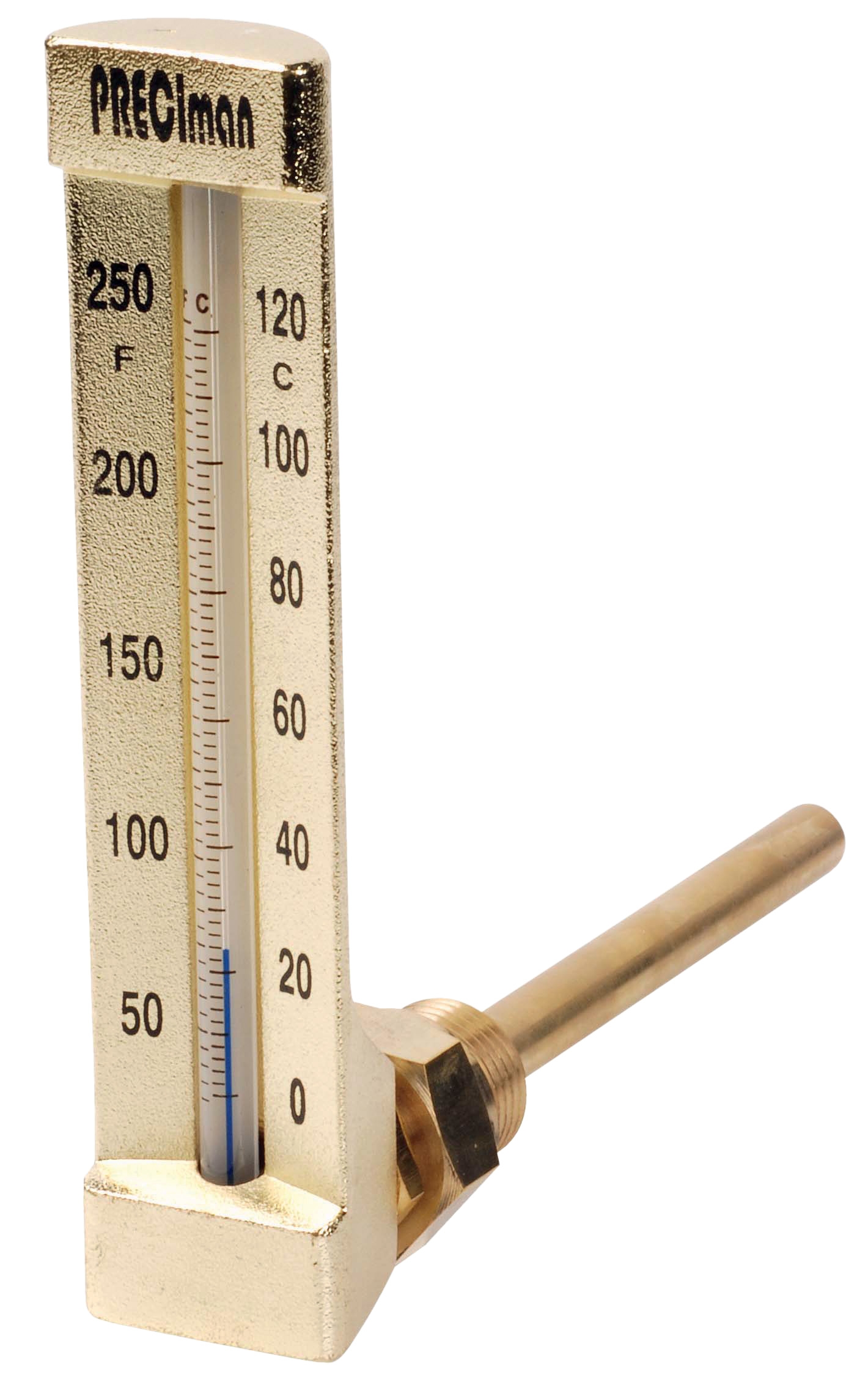
Temperature measurement devices like the CBM Axial Thermometer D65 -40/+40°C are particularly vulnerable because they experience continuous thermal stress. Electrical measurement systems using automated multimeters accumulate input impedance errors that compromise low-voltage measurements. Pressure expansion tanks lose accuracy when their battery-operated inflators like the CBM Expansion Tank Inflator 2000 mAH deplete without scheduled replacement.
This guide provides step-by-step procedures to identify which measurement systems are compromised, assess the urgency of recalibration, and restore data integrity to your industrial processes.
Diagnostic Testing Framework for Temperature Measurement Systems
Temperature sensors form the foundation of HVAC, refrigeration, steam systems, and process control. The challenge is that a 5°C drift in reading may not trigger alarms but will cost thousands in energy waste or product quality loss.
Three-Point Temperature Validation Method
Equipment needed:
- Reference thermometer (certified accuracy ±0.5°C)
- Ice water bath (0°C)
- Boiling water reference (100°C)
- Room temperature baseline (20-25°C)
1. Record baseline readings: Place your suspected thermometer and certified reference side-by-side at ambient temperature. Record both values. Acceptable drift is ±1°C for industrial-grade instruments.
2. Test ice point: Submerge both thermometers in ice water for 3 minutes. If your thermometer reads below -2°C or above +2°C while reference shows 0°C, suspect calibration loss.
3. Test boiling point: Transfer to boiling water. Reading should be 99-101°C. Readings below 95°C indicate significant drift requiring immediate recalibration.
4. Measure response time: Move thermometer from hot to cold water bath. Count seconds until reading stabilizes within 0.5°C. Industrial-grade thermometers should respond in 30-60 seconds. Response times exceeding 2 minutes suggest thermowell fouling or sensor degradation.
For vertical or larger thermometers like the CBM Green Vertical Thermometer D80 -30/+50°C L 10cm, perform the same test but allow additional soak time (5 minutes) due to larger mass.
Common Temperature Sensor Problems and Solutions
Problem: Reading drifts upward over time
- Cause: Thermal mass accumulation in thermowell, often from corrosion or mineral deposits
- Solution: Remove thermowell if accessible. Clean with soft brush and dilute vinegar. Flush with distilled water. Reinstall and retest
- Prevention: Establish quarterly thermowell maintenance schedule
- Cause: Thermowell insulation inadequate for process fluid velocity, or internal air pockets present
- Solution: Check for air bubbles in thermowell by tapping gently. Ensure thermowell immersion depth matches manufacturer specification (typically L5cm to L10cm). Consider increasing fluid circulation rate if possible
- Prevention: Document original commissioning specifications for comparison
- Cause: Different calibration ages, different immersion depths, or different fluid path exposure
- Solution: Batch test all thermometers simultaneously. Retire units with deviation >2°C. Standardize immersion depth and location for all new installations
- Prevention: Implement color-coded identification with calibration dates
The CBM Industrial Thermometer 0/+50°C immersion 63 is suited for field testing reference standards. Use this as your portable baseline for validating other temperature instruments.
Electrical Measurement and Detection Troubleshooting
Electrical measurement equipment including multimeters, insulation testers, and pressure transducers requires different validation approaches than mechanical sensors.
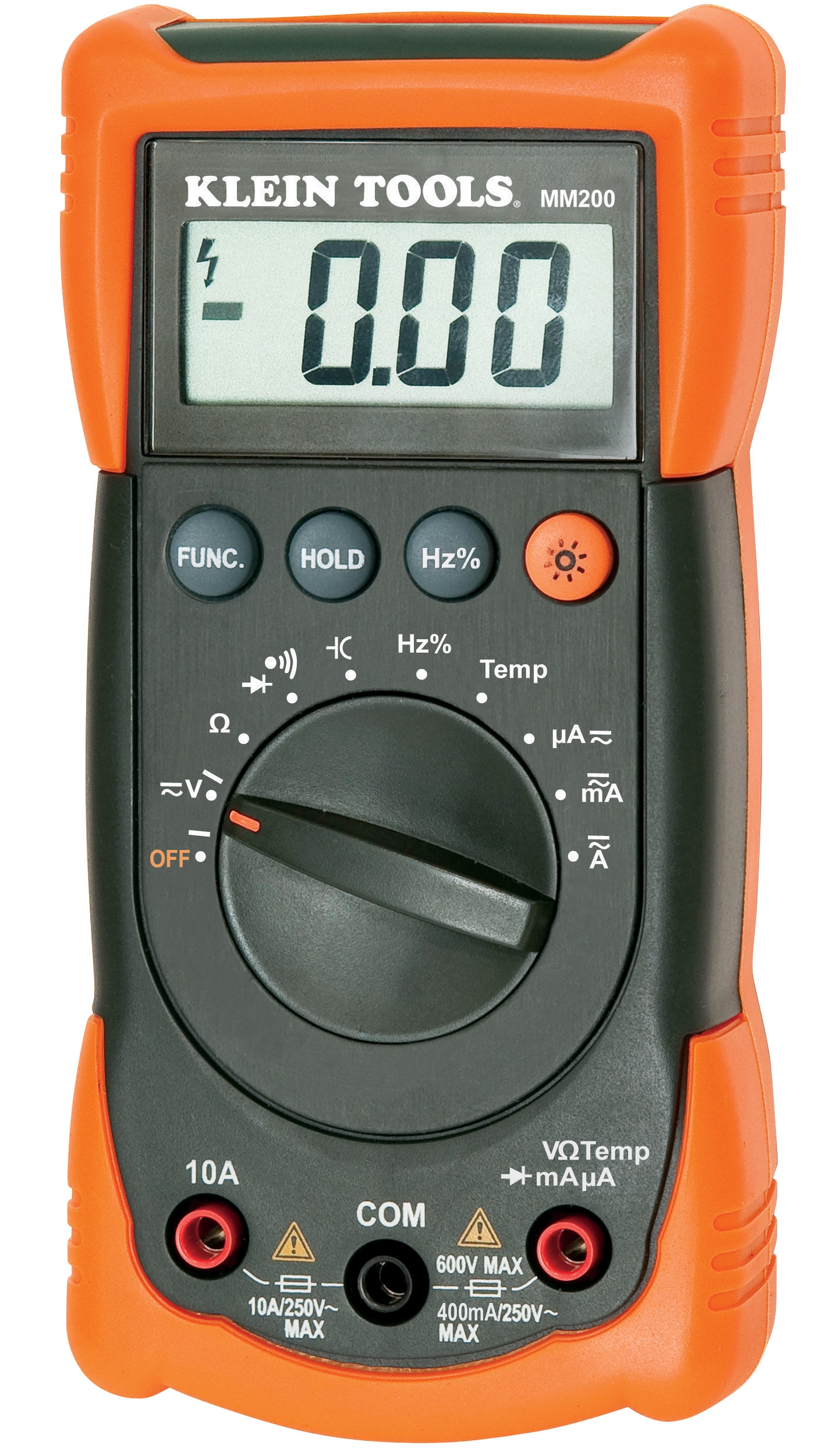
Multimeter Calibration and Input Impedance Verification
Automatic multimeters like the CBM Automatic Multimeter MM420 are susceptible to measurement drift in three critical ranges:
DC Voltage Measurement Errors
- Use certified voltage reference source (9V or 12V battery with ±1% accuracy tolerance)
- Test multimeter on 10V DC range; acceptable error is ±2% of reading (±0.2V)
- If error exceeds 2%, suspect battery depletion or internal calibration loss
- Battery voltage measurement drift commonly indicates internal resistance change requiring service
- Connect known precision resistors (100Ω, 1kΩ, 10kΩ ranges)
- Acceptable error: ±3% on standard ranges, ±5% on high impedance ranges
- Common failure: Reading open circuit (infinite resistance) when actual resistance is 10-50Ω suggests input protection diode failure
- If suspect, cease measurements immediately—device may damage circuits under test
- Current measurement requires breaking circuit; higher risk of damage and measurement loss
- Test with known current source if available; otherwise validate with voltage measurement across known load resistor and calculate using Ohm's law
- Current measurements drifting >5% usually indicate probe contact deterioration rather than internal meter failure
- Solution: Clean probe tips with pencil eraser and alcohol; replace frayed probe cables
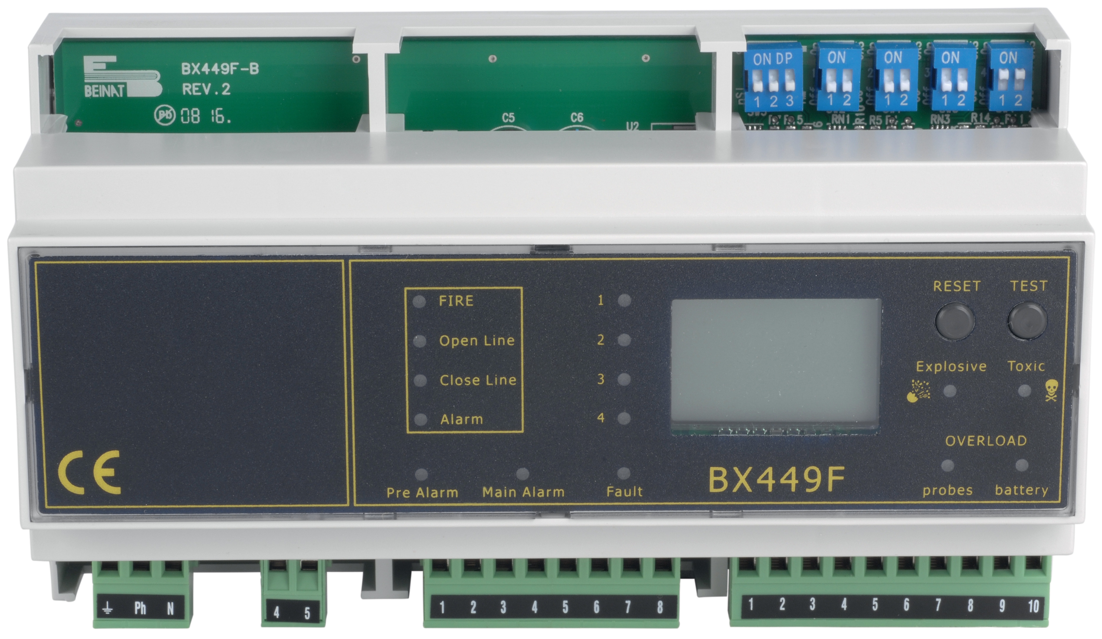
Pressure Transducer and Expansion Tank Monitoring
Pressure measurement systems fail when battery-powered components are neglected. The CBM Expansion Tank Inflator 2000 mAH battery is critical for maintaining accurate expansion tank precharge in closed-loop heating and cooling systems.
Pressure System Validation Procedure:
1. Verify battery condition: Expansion tank inflators must maintain 2000 mAH minimum capacity. Test battery voltage under load using multimeter DC voltage setting. Readings below 1.2V indicate replacement needed before pressure readings become unreliable.
2. Check expansion tank precharge: Isolate tank from system. Verify isolation valve closes completely (no slow pressure loss). Connect pressure gauge; should show stable reading. If pressure drops >0.2 bar over 15 minutes, suspect bladder rupture—tank requires replacement.
3. Validate transducer output: If equipped with 4-20mA pressure transducer, measure signal with multimeter on mA setting. At zero pressure (gauge isolation), signal should be 3.8-4.2mA. At maximum rated pressure, signal should be 19.5-20.5mA. Deviation >0.5mA indicates transducer calibration loss.
4. Cross-check with mechanical gauge: Install portable pressure gauge on test point. Compare reading to automated transducer output. Acceptable variance is ±2% of full scale reading.
Systematic Detection System Maintenance Protocol
Measurement & Detection systems require proactive monitoring to prevent silent failures that compromise process control.
Quarterly Calibration Assessment Schedule
Month 1 - Temperature Systems
- Perform three-point validation on all critical temperature sensors
- Document readings in maintenance log (spreadsheet or CMMS)
- Flag any sensor with drift >1°C for recalibration planning
- Clean accessible thermowell installations
- Test multimeters against certified voltage references
- Verify probe continuity and cable integrity
- Check battery voltages in portable instruments
- Replace batteries in expansion tank inflators if <80% capacity
- Validate expansion tank precharge against commissioning documentation
- Compare all pressure transducers to mechanical gauge baselines
- Verify 4-20mA signal linearity if equipped
- Document all deviations for technician review
- Simultaneously validate temperature, pressure, and electrical measurement on same system
- Identify cross-system delays or inconsistencies
- Review process control performance for hunting or instability
- Plan recalibration for out-of-tolerance instruments
Documentation and Traceability
Maintain calibration records including:
- Instrument ID and location
- Manufacturer specifications and acceptable tolerance ranges
- Test date and test method used
- Baseline and current readings
- Trend analysis (drift rate in units per month)
- Corrective actions taken
- Scheduled recalibration or replacement dates
Instruments with drift rates exceeding 0.5% per month should be expedited for professional recalibration or replaced rather than monitored further.
Summary: Building Measurement Reliability Into Maintenance Operations
Measurement & Detection system failures represent invisible process control degradation that destroys efficiency and product quality gradually. 3G Electric's 35+ years of experience show that maintenance teams that implement systematic quarterly validation catch 92% of sensor failures before they impact operations.
Your immediate action items:
1. This week: Identify all critical temperature and pressure measurement points in your facility
2. This month: Perform baseline three-point temperature validation and multimeter testing
3. Quarterly: Implement the assessment schedule outlined above
4. Annually: Send out-of-tolerance instruments for professional recalibration
5. Continuously: Replace batteries in expansion tank inflators and maintain calibration logs
The cost of quarterly validation testing (typically 4-6 hours labor per facility) is recovered within one month through reduced energy waste, improved process control, and prevented quality losses. Professional recalibration of instruments costs $150-400 per device but extends service life 5+ years and prevents cascading system failures.
Contact 3G Electric for calibrated reference standards, replacement transducers, and battery supplies like our CBM expansion tank inflator, automatic multimeters, and axial thermometers to support your measurement system maintenance program.