Understanding Maintenance & Service Requirements for Industrial Fluid Systems
Maintenance & Service protocols form the foundation of reliable industrial equipment operation. Procurement engineers responsible for specifying and managing industrial fluid systems must understand that preventive maintenance directly impacts equipment availability, safety compliance, and total cost of ownership. Unlike reactive troubleshooting, systematic Maintenance & Service programs identify degradation patterns before critical failures occur.
With over 35 years distributing industrial equipment globally, 3G Electric has observed that organizations implementing structured Maintenance & Service schedules reduce unplanned downtime by 40-60% compared to failure-driven maintenance approaches. The key distinction lies in understanding which components require condition-based monitoring versus time-based servicing, and how environmental factors in different regions affect maintenance intervals.
Industrial fluid systems—including expansion tanks, nozzle assemblies, and alarm/shut-off mechanisms—operate under dynamic stress. Temperature fluctuations, pressure cycling, and fluid degradation accumulate gradually. Effective Maintenance & Service programs establish baseline performance metrics, then deploy diagnostic techniques to detect deviation from normal operating parameters.
Diagnostic Framework for Expansion Tank and Pressurization Systems
Pressure Integrity Assessment
Expansion tanks are critical components that absorb volumetric changes in circulating fluids. Maintenance & Service protocols must include quarterly pressure verification. The CBM Expansion tank inflator battery 2000 mAH represents the intersection of preventive maintenance and component accessibility. Procurement engineers should specify this tool during initial equipment commissioning to establish baseline pressure documentation.
Diagnostic procedure:
- Measure static pressure with system offline and cooled to ambient temperature
- Compare against system design specification (typically 0.9× minimum operating pressure)
- Document pressure loss rate over 30-day intervals
- If pressure drops exceed 5% monthly, investigate for membrane degradation or connection leaks
Pressure loss patterns reveal failure mechanisms. Rapid pressure loss (>10% weekly) indicates membrane rupture, requiring tank replacement. Gradual loss suggests connection corrosion or microscopic leakage at threaded unions. This distinction determines whether technicians require invasive inspection or can execute simple tightening procedures.
Tank Mounting and Structural Integrity
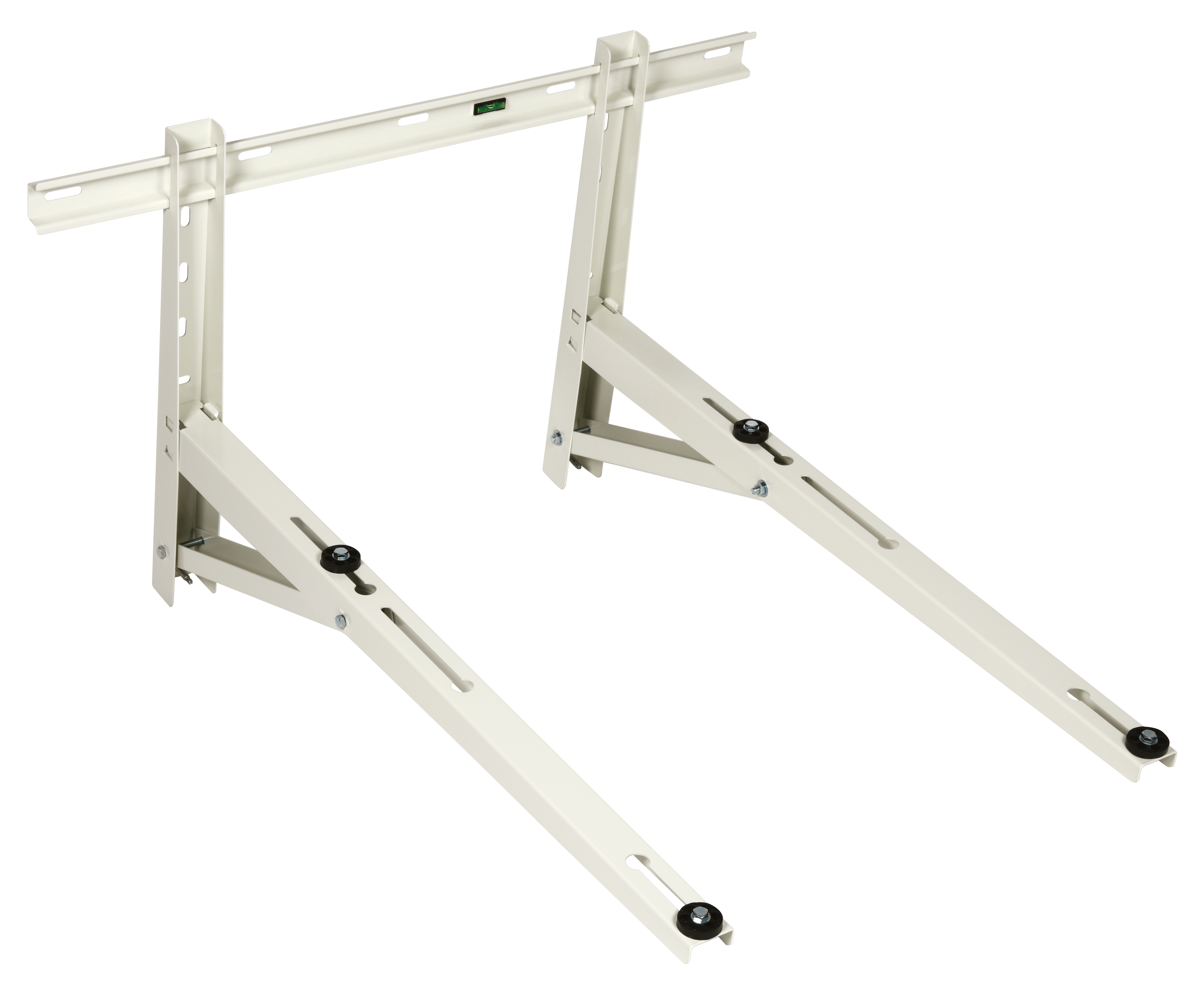
Expansion tanks experience vibration-induced stress, particularly in mobile or dynamically-loaded applications. The CBM Wall bracket 1000 provides structural stabilization that reduces resonant frequency issues. Maintenance & Service inspections should verify bracket fastener torque quarterly—vibration gradually loosens connections, creating secondary leakage paths.
Inspection protocol:
- Visually examine brackets for deformation, cracking, or corrosion
- Apply lateral force to tank assembly; confirm movement <5mm at fastening points
- Verify bracket bolt torque against original specifications
- Monitor for corrosion products at mounting interface (indicates galvanic coupling issues)
Nozzle Assembly Maintenance & Service Diagnostics
Flow Pattern Verification and Atomization Assessment
Flat jet nozzles, including the CBM Flat jet nozzle HP 1/4"M BSPT index 25 angle 15° and CBM Flat jet nozzle HP 1/4"M BSPT index 055 angle 15°, deteriorate through fluid erosion and thermal stress. Unlike pump or valve failures producing sudden shutdowns, nozzle degradation manifests as performance drift—reduced output, altered spray geometry, or inconsistent atomization patterns.
Maintenance & Service diagnostic methodology:
Visual Assessment Protocol: Under operating conditions, observe spray cone angle and width. Degraded nozzles exhibit narrower spray patterns or asymmetrical dispersion. Document photographic reference images during commissioning to establish baseline.
Pressure-Flow Correlation: Measure fluid pressure at nozzle inlet and volumetric flow rate. Compare against manufacturer's rated curve. A nozzle rated for 25 index (approximately 1.9 gal/min at 100 PSI) flowing only 1.6 gal/min at identical pressure indicates 16% capacity loss—typical degradation threshold requiring replacement.
Dimensional Verification: Nozzle orifice erosion can be assessed through dye-tracer testing. Inject colored tracer fluid and observe penetration depth and spread. Increased spread with constant pressure indicates enlarged orifice diameter.
Procurement engineers should establish replacement intervals based on operating hours rather than calendar time. Industrial burner systems operating 8+ hours daily should schedule nozzle replacement every 18-24 months; intermittent systems (seasonal operation) can extend intervals to 3 years.
Internal Debris and Filtration Requirements
Nozzle fouling represents 30-40% of all nozzle-related performance issues in industrial settings. Maintenance & Service programs must establish filtration requirements upstream of nozzle assemblies. Fluid cleanliness standards (typically ISO 4406 code 18/16/13 or better) prevent accumulation of abrasive particles that accelerate erosion.
Diagnostic indicators of fouling:
- Pressure rise at nozzle inlet while flow decreases
- Increased system noise or vibration
- Irregular spray pattern with localized dead zones
- Nozzle outlet temperature anomalies detected via thermal imaging
Alarm and Shut-off System Monitoring
Functional Testing and Response Verification
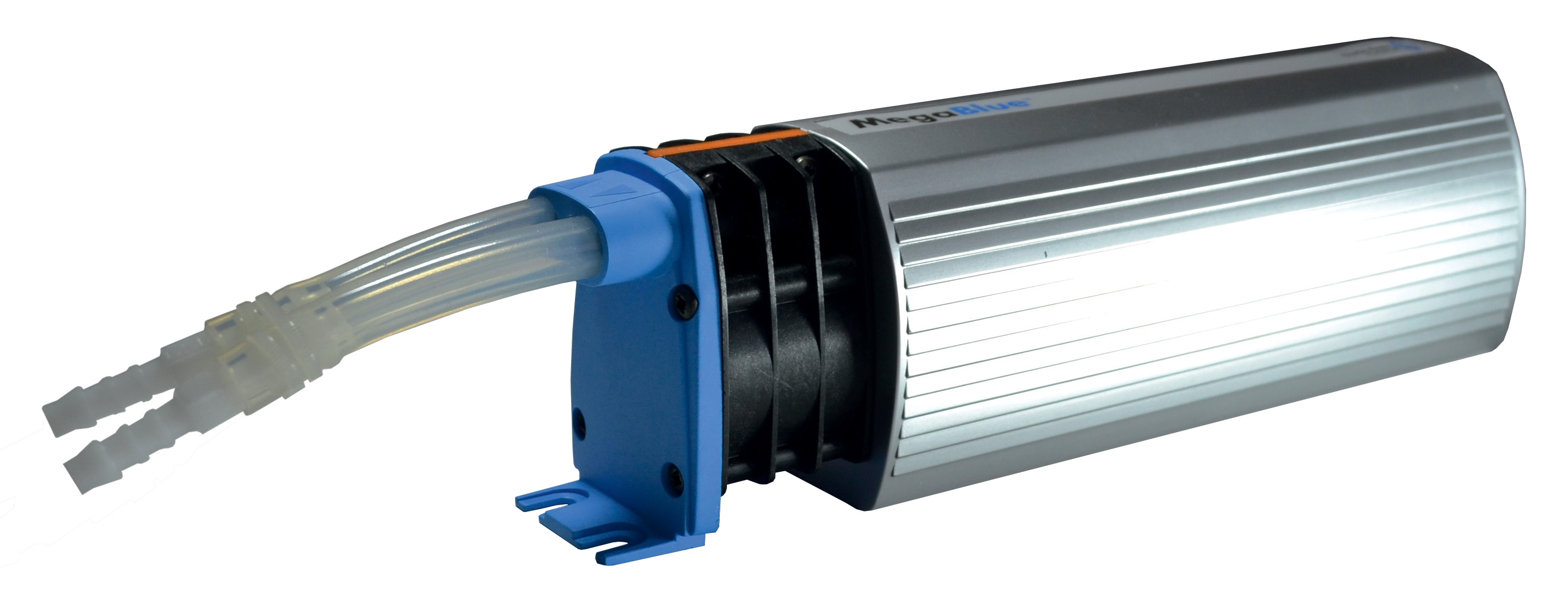
The CBM Megablue reservoir alarm + shut-off X87-813 integrates sensing, signaling, and actuation functions. Maintenance & Service protocols must include functional testing distinct from component inspection. An alarm unit may appear visually intact but fail to activate under actual trigger conditions due to sensor drift or electrical degradation.
Monthly Functional Testing:
- Manually simulate alarm trigger condition (low level, high temperature, or pressure deviation)
- Verify alarm signal produces audible/visual indication within 2 seconds
- Confirm shut-off valve closure within specified response time (typically <5 seconds)
- Document test date, technician ID, and pass/fail status
Sensors require calibration every 12 months in high-vibration environments, 18-24 months in stable installations. Procurement engineers should budget for calibration services during initial equipment specification, as post-purchase calibration adds 30-40% to component cost due to logistics and documentation requirements.
Electrical Contact and Wiring Assessment
Alarm systems rely on reliable electrical connections—a failure mode often overlooked in Maintenance & Service protocols. Vibration, temperature cycling, and moisture ingress degrade contact surfaces gradually.
Diagnostic approach:
- Measure contact resistance at alarm signal terminals (target: <0.1 ohms)
- If resistance exceeds 0.5 ohms, disassemble connector and inspect for oxidation
- Clean contacts with electrical contact cleaner; verify resistance drops below threshold
- Apply contact protectant (dielectric grease) to inhibit oxidation
- Verify wiring insulation integrity via megohm resistance test (target: >10 megohms at 500V DC)
Connector corrosion accelerates in humid, coastal, or chemically aggressive environments. Organizations in these regions should implement 6-month contact maintenance cycles rather than standard 12-month intervals.
Establishing Maintenance & Service Programs: Implementation Strategy for Procurement Engineers
Documentation and Baseline Establishment
Effective Maintenance & Service programs require comprehensive baseline documentation established during commissioning. Procurement specifications should mandate:
- Photographic documentation of all assemblies in initial condition
- Pressure/temperature baseline measurements under standard operating loads
- Flow rate verification against design specifications
- Electrical continuity and resistance measurements
- Vibration profiles at key mounting points
This baseline becomes the reference standard for all subsequent diagnostic activities. Deviations exceeding ±10% warrant investigation; deviations exceeding ±20% typically require component replacement.
Regional Environmental Considerations
Maintenance & Service intervals and protocols must account for geographic operating environments. 3G Electric's global distribution network has documented that:
Tropical/Humid Regions: Increase corrosion monitoring frequency; implement monthly visual inspections for oxidation at connection points. Expand electrical testing intervals to 6-month cycles.
Desert/High-Temperature Environments: Fluid degradation accelerates 2-3× faster than temperate climates. Reduce nozzle service intervals by 25-30%. Monitor expansion tank pressure monthly (vs. quarterly) due to increased thermal cycling.
Industrial/Contaminated Environments: Implement monthly filter replacement instead of quarterly; increase vibration monitoring to weekly during critical season operation. Budget for more frequent connector maintenance due to airborne contaminants.
Cold Climate Regions: Fluid viscosity increases; pressure relief settings may require seasonal adjustment. Expansion tank pressure verification becomes critical in winter months due to fluid contraction. Implement heated storage for backup nozzles to prevent thermal shock during installation.
Compliance and Regulatory Alignment
Maintenance & Service documentation serves regulatory compliance functions beyond operational efficiency. Organizations must establish procedures that demonstrate Due Diligence in equipment stewardship. Documentation should include:
- Maintenance schedule with scheduled vs. actual completion dates
- Test results with pass/fail criteria clearly defined
- Corrective action records linking identified issues to remediation
- Component replacement records with serial numbers and disposal documentation
- Calibration certificates for all test instruments
This systematic approach protects procurement and engineering departments from liability claims while demonstrating compliance with ISO 9001 quality standards and industry-specific regulations (ASME, API, etc.).
Best Practices for Long-Term Component Reliability
Procurement engineers can maximize equipment reliability through specification decisions that facilitate Maintenance & Service execution:
Modular Design Preference: Specify systems with replaceable, standardized components rather than integrated assemblies. The CBM Flat jet nozzle HP 1/4"M BSPT index 25 angle 15° and CBM Flat jet nozzle HP 1/4"M BSPT index 055 angle 15° use standard BSPT connections enabling field replacement without specialized tools.
Diagnostic Port Specification: Require pressure/temperature measurement ports at critical system locations. These enable technicians to execute Maintenance & Service diagnostics without system shutdown or invasive disassembly.
Spare Parts Inventory: Establish minimum spare parts inventory for high-criticality systems. Typical recommendation: 20% of installed base for consumable components (nozzles, filters), 5% for wear items (seals, gaskets), 100% backup for single-point-of-failure components (critical shut-off valves).
Training and Competency: Invest in technician training specific to your installed equipment. Maintenance & Service quality directly correlates with technician knowledge. Organizations implementing annual training programs report 25-35% fewer diagnostic errors compared to untrained personnel.
With 35+ years serving global industrial markets, 3G Electric emphasizes that effective Maintenance & Service programs represent strategic investments yielding 3-5 year payback periods through reduced downtime costs and extended equipment life cycles.