Understanding Gas Valves & Regulation in Your Facility
Gas Valves & Regulation form the backbone of safe, efficient industrial gas systems. Whether you're managing burners, heating systems, or process gas lines, understanding how these components interact helps your maintenance team make informed decisions about repairs, replacements, and system optimization.
At 3G Electric, we've supported maintenance operations across manufacturing, food processing, chemical plants, and energy facilities for over 35 years. We've seen that most valve failures aren't catastrophic overnight events—they're the result of missed early warning signs. Pressure creep, flow fluctuations, unexpected pilot light extinguishment, and temperature instability all indicate your gas regulation system needs attention.
The key difference between reactive and predictive maintenance lies in understanding what normal operation looks like at your facility. Each industrial environment has unique pressure profiles, temperature ranges, and flow demands. Your maintenance team must establish baseline performance data, monitor for deviations, and address issues before they impact production or safety.
Diagnostic Protocols: Reading Your System's Signals
Pressure Stability Monitoring
Your regulation system's primary job is maintaining consistent downstream pressure despite upstream fluctuations. Unstable pressure indicates the regulator isn't functioning properly.
What to monitor:
- Downstream pressure oscillation (should be ±5% maximum in most applications)
- Response time when upstream pressure changes
- Drift over extended operation periods (12+ hour runs)
- Correlation between pressure changes and equipment performance issues
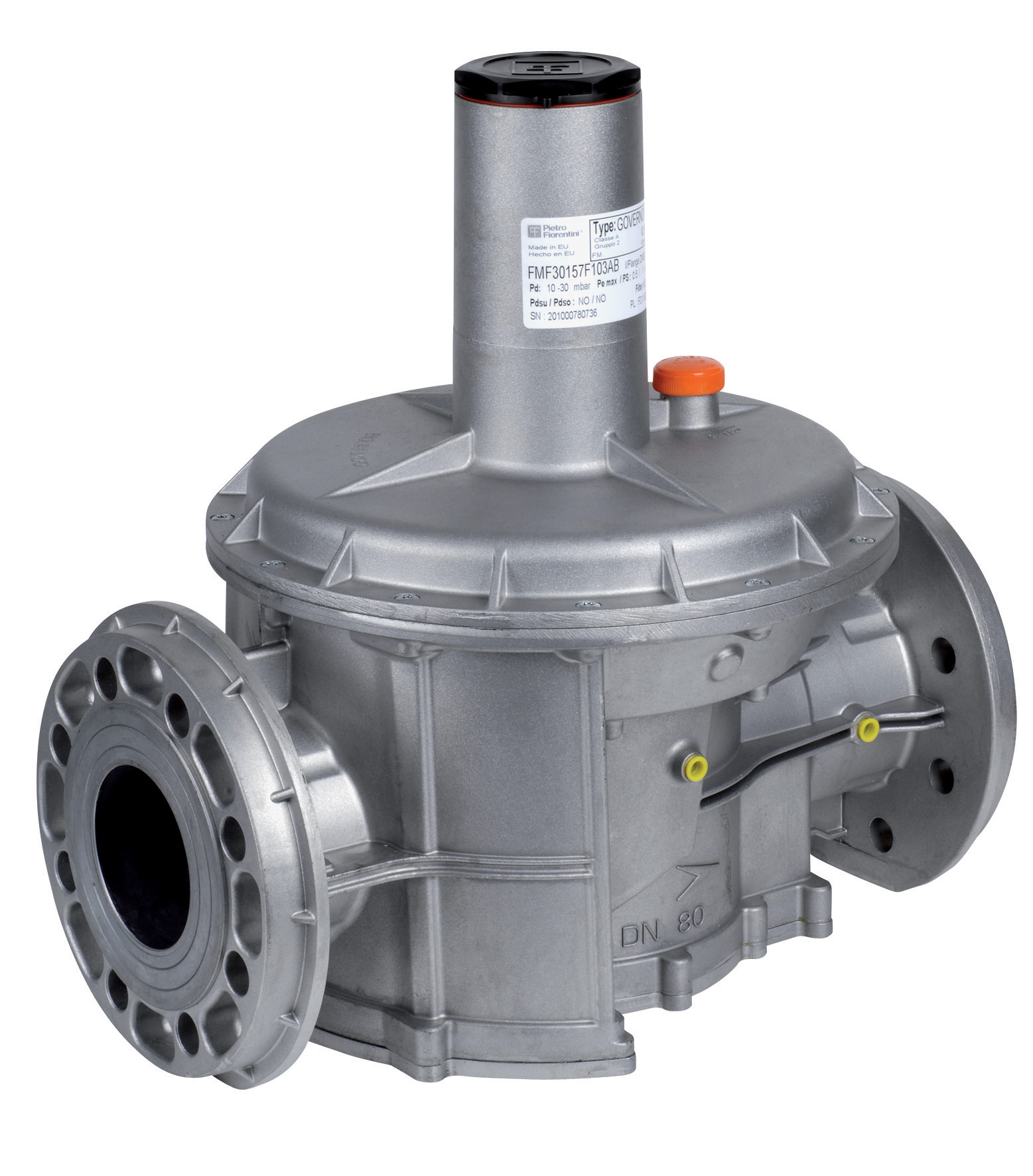
If you're experiencing pressure swing of more than 10% during operation, your regulator diaphragm likely has micro-tears or the valve seat shows wear. The CBM Pressure regulator threaded D1"1/2 500 Mbar PS 5/300 Mbar maintains precise regulation through its robust diaphragm design, but even quality regulators require periodic inspection.
Diagnostic steps:
1. Install secondary pressure gauge downstream of your regulator (if not already present)
2. Record pressure readings every 15 minutes during normal operation
3. Note any correlation between pressure fluctuations and visible equipment behavior (flame height, heating output, etc.)
4. Calculate pressure variance coefficient—readings within 3-5% of setpoint indicate healthy operation
5. Document baseline data for future comparison
Flow Rate Verification
Declining flow rates often precede complete regulator failure. Gas consumption increase while maintaining same production output signals obstruction or internal regulator degradation.
How to check:
- Compare current gas meter readings against historical usage for equivalent production runs
- Monitor burner flame appearance—orange/yellow discoloration indicates lean mixture from inadequate gas flow
- Note if heating zones show uneven temperature distribution
- Track operating hours between regulator inspections
For larger systems using CBM Pressure regulator with flanges DN50 500 Mbar PS 5/300 Mbar or CBM Pressure regulator with DN65 flanges 500 Mbar PS 5/300 Mbar, flow degradation becomes apparent through reduced throughput and longer startup times to reach target temperatures.
Pilot Light and Ignition System Assessment
Pilot light failures often point to gas supply quality issues or regulator problems affecting pilot gas delivery. This is typically your first warning sign before main system failure.
Assessment protocol:
1. Check pilot light flame color (should be bright blue with slight yellow at tip)
2. Observe flame height consistency over 5-minute observation period
3. Note any hesitation when main burner ignites
4. Record ambient temperature and humidity conditions
5. Test pilot relight cycles—should ignite reliably within 2-3 seconds
The CBM 1-flame pilot light 0.150.082 requires consistent gas delivery pressure of 3.5-4.5 mbar. If your pilot light exhibits flickering or intermittent extinction, measure regulator output pressure—readings below 3 mbar indicate regulator malfunction requiring immediate attention. Higher than 5 mbar suggests blockage in the pilot line or regulator seat degradation.
Maintenance Procedures: Extending Component Life
Quarterly Inspection Routine
Establish a quarterly (13-week) inspection cycle for all gas regulation systems:
External examination (15 minutes):
- Inspect regulator body for corrosion, particularly at threaded connections
- Check all connection points for frost or condensation accumulation—indicates potential leak or pressure drop
- Verify gauge glass clarity on any installed pressure indicators
- Confirm all adjustment lockwire or tamper seals remain intact
- Document any visible contamination (dust, oil residue, etc.) on external surfaces
- Record upstream and downstream pressures at minimum, half, and full load conditions
- Log ambient temperature, gas supply temperature, and any process changes
- Photograph gauge readings for your maintenance database
- Compare current readings to previous quarter—pressure drift exceeding 2% between quarters signals internal wear
- Confirm main shut-off valve operates smoothly through full range
- Test emergency cutoff response time (should be less than 2 seconds)
- Verify all pressure relief openings are unobstructed
- Check for gas odor near connections (indicates leakage)
Annual Deep Maintenance
Once yearly, schedule comprehensive regulator service:
Disassembly and cleaning:
- Document regulator configuration before opening (take photos of adjustment settings)
- Remove cover and inspect diaphragm for tears, surface degradation, or deposits
- Clean all internal passages with compressed air—never use solvents that leave residue
- Inspect valve seat for pitting or erosion using bright light and magnification
- Check spring for corrosion or deformation
- Measure diaphragm thickness at center point—should be uniform; thinning indicates material fatigue
- Verify spring compression force by measuring free height against manufacturer specifications
- Inspect gasket surfaces for scoring—light surface damage is acceptable, but deep grooves require face replacement
- Document any anomalies for procurement team
- Rebuild regulator per manufacturer sequence (critical for proper diaphragm seating)
- Apply thin oil film (ISO 32 mineral oil only) to diaphragm surfaces
- Test pressure setting using calibrated test gauge before returning to service
- Perform 24-hour stability test—pressure drift should not exceed ±1% during this period
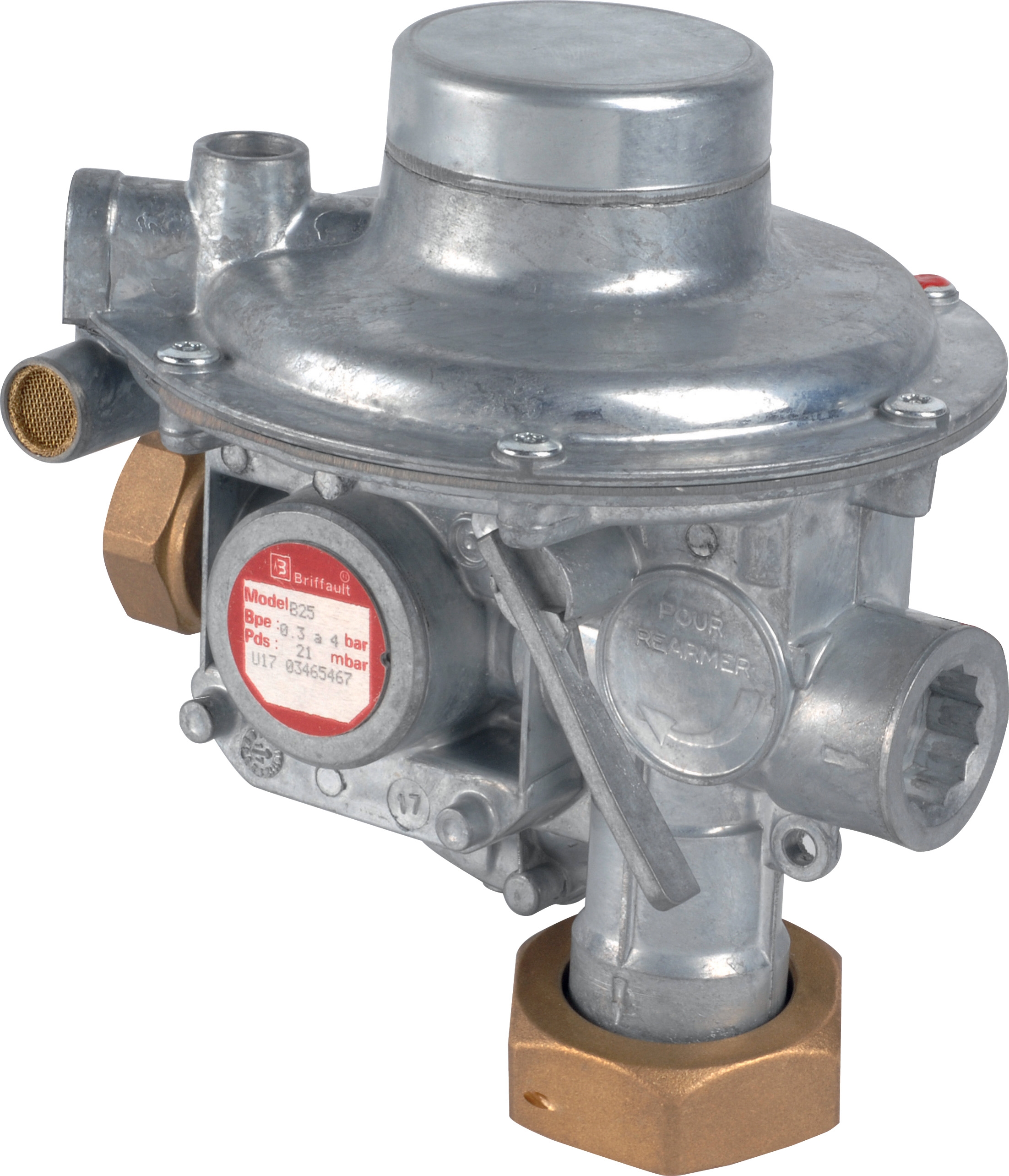
For systems using the CBM Regulator Francel B10/37mbar with safety, this model's integrated safety function requires special attention during reassembly. The safety valve ball must move freely—clean with compressed air only, never soak in solvents.
Identifying Replacement Triggers
Don't wait for complete failure. Replace regulators when:
- Pressure oscillation exceeds ±8% despite adjustment attempts
- Flow rate has declined 15% below baseline while operating conditions remain constant
- Diaphragm shows visible tears or deep pitting during inspection
- Adjustment range decreases (can no longer achieve design pressure settings)
- Safety valve fails to vent during overpressure simulation test
- Internal components show corrosion despite clean fuel supply
- Regulator has operated continuously for 5+ years without major service
System Integration and Performance Optimization
Gas Supply Quality Impact
Your regulator's performance depends directly on upstream supply quality. Contaminants, moisture, and pressure variations compromise even premium regulators.
Maintenance team responsibilities:
- Install or verify inlet strainers rated for gas service (minimum 150 microns)
- Change inlet filter elements every 6 months in dusty environments, annually in clean facilities
- Monitor for water accumulation in supply lines—install drains at system low points
- Document supply pressure from main source—excessive fluctuation indicates utility-side issue
- Maintain inlet pressure within regulator specifications (typically 1.5× minimum operating pressure)
Pilot Gas Line Integrity
Pilot systems operate at much lower pressures (3-5 mbar), making them vulnerable to blockage and contamination.
Pilot system maintenance:
- Trace pilot line from regulator outlet to pilot light; check for kinks, crushing, or pinching
- Inspect all pilot line connections for tightness using appropriate wrenches
- Verify pilot line diameter matches original design (smaller diameter increases flow restriction)
- Confirm pilot gas shutoff valve (if installed) operates smoothly
- Clean pilot orifice annually using soft brass brush—never steel wire or hard tools
- Test pilot pressure at regulator outlet using low-range gauge (0-10 mbar scale)—should be 4-5 mbar at idle
Pressure Gauge Maintenance
Your measurement instruments affect diagnostic accuracy.
Gauge care:
- Verify gauge calibration every 12 months against certified standard
- Replace gauges showing erratic needle movement or sticking
- Install snubber valves upstream of gauges for burner applications (vibration protection)
- Ensure gauge isolation valves remain accessible for safe removal
- Document gauge serial numbers and calibration dates in maintenance log
Practical Troubleshooting Decision Tree
Symptom: Low downstream pressure
- Measurement verified with calibrated gauge? (If no, replace gauge first)
- Is inlet pressure adequate (check against specifications)? (If no, contact fuel supplier)
- Does adjusting regulator screw increase pressure? (If no, diaphragm likely failed—replacement required)
- Can you hear hissing at relief vent during adjustment? (If no, relief path blocked—disassembly needed)
- Oscillation correlates with load changes? (Yes = regulator sensitivity acceptable, check downstream demand)
- Oscillation continues at constant load? (Yes = internal wear, schedule replacement)
- Does oscillation amplitude increase over hours of operation? (Yes = spring fatigue, replacement recommended)
- Does pilot relight immediately and stay lit? (Yes = pilot gas supply intermittent, check inlet filter and shut-off valve)
- Does pilot ignite but immediately extinguish? (Yes = pilot orifice blocked, requires cleaning)
- Does ambient wind affect pilot persistence? (Yes = pilot light design inadequate for location—relocate or shield)
35 Years of Industrial Experience Behind Your Maintenance Program
3G Electric has supported maintenance teams since 1990, accumulating decades of field experience with gas regulation systems across diverse industries. We understand that maintenance budgets are finite, and equipment must perform reliably under demanding conditions.
The products we distribute—from the robust CBM threaded pressure regulator for compact installations to the high-capacity CBM flanged regulators for DN65 piping—have proven performance records in thousands of facilities worldwide. But equipment is only as reliable as the maintenance program supporting it.
Your maintenance team's expertise in recognizing early warning signs, establishing baseline performance data, and executing systematic inspections represents the true foundation of operational reliability. The diagnostic protocols and procedures outlined here synthesize best practices from installations we've serviced, updated for current equipment standards and safety requirements.
When you need replacement components or consultation on system upgrades, 3G Electric's technical team brings this same decades-long perspective to your specific challenges. We help maintenance teams make informed decisions about when to repair, when to replace, and how to optimize system performance within operational constraints.