Combustion Air Management & Forced Draft Control: Technical Guide for Industrial Burner Systems
Effective combustion air management represents one of the most critical yet frequently misunderstood aspects of industrial burner operation. Whether you manage a fleet of burners across multiple facilities or troubleshoot a single failing installation, understanding how air supply, pressure regulation, and flame stability controls work together directly impacts equipment reliability, fuel efficiency, and operational safety. This guide explores the technical foundations of forced draft combustion systems, the role of air pressure management in flame stability, and practical diagnostic approaches that maintenance teams use globally to optimize burner performance.
Understanding Forced Draft Combustion Architecture
Forced draft burners employ a high-pressure fan system to deliver a controlled, pressurized air supply to the combustion chamber. Unlike naturally aspirated systems that rely on buoyancy and chimney draft, forced draft designs give operators precise control over air-fuel ratios, combustion intensity, and flame geometry—critical advantages for industrial applications where performance consistency and emissions control are non-negotiable.
The core architecture comprises three functional zones: the air intake and filtration system, the pressurization fan assembly, and the combustion head with its distribution and stabilization components. Air enters through a filtered intake, accelerates through the fan (typically 370-500W motor capacity for compact industrial units), and exits at controlled pressure into the burner's combustion head where it mixes with fuel and ignites.
Pressure management within the burner's air circuit directly determines flame characteristics. Natural gas burners typically require minimum air pressures between 27-33 mbar at the burner inlet to establish stable ignition and maintain proper flame shape. Insufficient air pressure produces weak, unstable flames prone to flame-out; excessive pressure creates turbulent combustion with poor mixing and uncontrolled flame spread. The forced draft fan's variable speed operation—when controlled by modulation systems—allows real-time pressure adjustment to match the fuel flow demand, maintaining optimal combustion conditions across the full operating range.
Modern forced draft systems incorporate combustion heads designed for high efficiency and flame stability. These components feature precision air distribution slots, swirl generators that create rotational air flow patterns, and adjustable stabilizers that establish the correct flame anchoring point. Together, these mechanical features ensure that fuel introduced into the air stream burns completely, uniformly, and safely—regardless of load fluctuations or minor variations in fuel supply characteristics.
Air Pressure Regulation, Safety Interlocks & Control System Integration
Industrial forced draft burners operate within a tightly managed control framework that continuously monitors air pressure, fuel pressure, and flame presence. The air pressure regulation subsystem—typically incorporating a motorized damper or variable fan speed drive—maintains supply pressure within the design operating band. Pressure sensors provide feedback signals to the burner control system, which compares actual air pressure to programmed setpoints and adjusts fan motor speed or damper position to maintain target conditions.
Safety interlocks represent a critical component of this architecture. Most industrial burner controllers incorporate an air pressure switch that prevents fuel delivery unless adequate air flow has been established. This interlock sequence typically requires 15-30 seconds of forced air circulation through the combustion chamber before the ignition transformer and fuel solenoid valves are energized. If air pressure drops below the minimum threshold during operation—indicating fan failure, duct blockage, or filter saturation—the control system immediately shuts off fuel and locks out the burner, preventing unburned fuel accumulation in the combustion chamber.
The CBM CM391.2 30.5 relay exemplifies the control architecture used in modern forced draft gas burner systems. This intermittent automatic gas burner control device coordinates the sequence of air supply verification, ignition authorization, fuel delivery, and flame monitoring. Its non-volatile lock-out function ensures that any failure during the startup sequence (such as failure to establish ignition within 5 seconds) triggers immediate fuel shutdown and requires manual reset—preventing dangerous fuel accumulation.
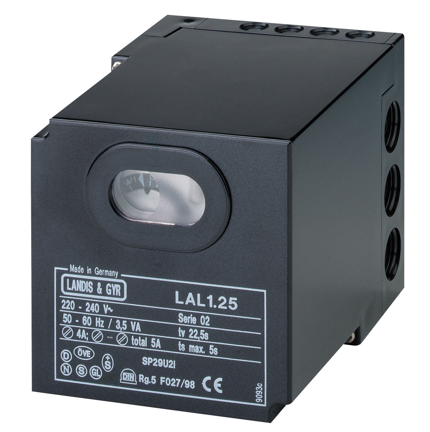
For oil-fired forced draft applications, the CBM LAL 2.14 safety relay provides similar protective sequencing. Designed for intermittent service across universal burners and hot air generators, this control system manages air pressure authorization, monitors fuel flow conditions, and coordinates flame detection signals from devices like infrared sensors or photoelectric cells. The integration of air pressure sensing with flame supervision creates a redundant safety architecture where combustion can only proceed when both air delivery and flame presence are confirmed.
The CBM IRD 1010 blue cell infrared flame detector operates as the flame monitoring component in this control loop. With a spectral sensing range of 800-1100 nm (optimized to 950 nm with daylight filtering), this detector recognizes the infrared signature of active fuel flame. Its mounting flexibility—allowing installation at any orientation—accommodates diverse burner geometries. The detector's 15-250 Hz frequency response captures the natural flicker of turbulent flames while rejecting electrical noise and stray light interference, providing reliable flame confirmation signals to the safety relay even in challenging industrial environments.
Real-World Application: Multi-Fuel Industrial Heating Systems
Consider a manufacturing facility operating steam boilers fed by forced draft burners that must alternate between natural gas and LPG depending on seasonal supply and cost optimization. Each fuel type demands slightly different combustion air characteristics: natural gas requires precise air pressure around 27-30 mbar, while LPG (being heavier) achieves optimal mixing at 30-33 mbar. The forced draft system's adjustable fan motor and pressure regulation allow seamless transition between fuel types without mechanical redesign.
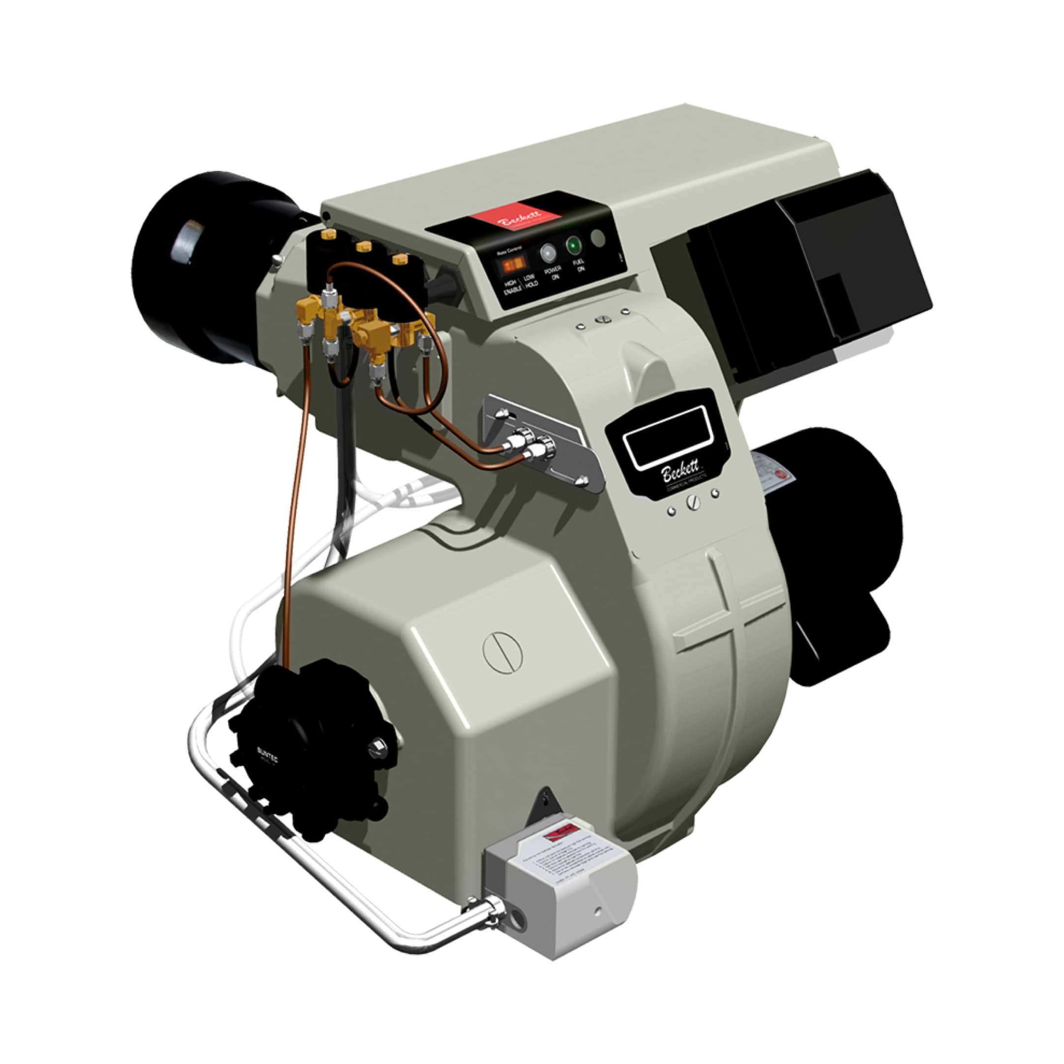
The FBR BURNER GAS X5/MF TL burner specifically addresses this multi-fuel requirement. Its die-cast aluminum combustion head incorporates adjustment mechanisms for high efficiency operation across the I2R, I2H, I2L, I2E, and I3B/P fuel categories—covering both natural gas and liquefied petroleum gas applications. The unit's maximum power output of 349 kW and minimum output of 69.8 kW defines a 5:1 turndown ratio, permitting operation across variable load demands within a single facility.
When such a burner experiences intermittent flame dropout or unstable ignition, maintenance teams systematically diagnose the root cause by first verifying forced draft air pressure at the burner inlet. A simple manometer reading reveals whether the fan motor is delivering adequate pressure. Next, technicians verify that the air intake filter isn't clogged (a common cause of pressure loss), inspect the combustion head's fuel nozzle for obstruction, and confirm that the flame detector (often an infrared cell like the CBM IRD 1010) is receiving clear line-of-sight to the flame zone. In many cases, a clogged fuel nozzle combined with borderline air pressure creates exactly the conditions for intermittent ignition failure.
Selection Criteria & Maintenance Best Practices
When specifying or maintaining forced draft combustion systems, prioritize these technical factors:
Fan Motor Capacity & Pressure Range: Ensure the fan motor's continuous power rating (typically 370-500W for industrial burners) exceeds the maximum static pressure required by the combustion head. Undersized fans produce insufficient pressure; oversized fans waste energy and risk overheating the combustion chamber.
Control System Sequencing: Verify that the burner controller enforces the correct startup sequence: air circulation (15-30 seconds minimum), ignition confirmation (within 5 seconds), fuel valve opening, and continuous flame monitoring. Any deviation indicates control system failure or incorrect configuration.
Flame Detection Redundancy: For critical applications, specify dual flame detectors or controllers that support multiple sensor types (infrared cells, photoelectric sensors, or ionization probes) operating in parallel. This redundancy ensures that single sensor failure doesn't disable the entire burner.
Preventive Air Circuit Maintenance: Replace intake air filters on a quarterly schedule (or whenever pressure drop exceeds 50 Pa). Accumulating dust in the filter directly reduces fan output pressure and destabilizes combustion. Inspect combustion head air distribution slots annually to ensure they haven't become clogged with soot or debris.
Pressure Gauge Installation: Install accessible pressure gauges on both the air supply line upstream of the burner and the combustion chamber itself. This allows real-time diagnostics without disassembling the system. Normal operating air pressure should match the burner manufacturer's published specification (e.g., 27-33 mbar for natural gas burners).
Conclusion & Next Steps
Mastering combustion air management transforms how maintenance teams approach burner reliability and optimization. By understanding the interconnection between forced draft fan operation, air pressure regulation, safety interlock sequencing, and flame detection, you gain the diagnostic framework needed to quickly isolate root causes and implement lasting solutions. Whether you're managing a single burner or coordinating fleet-wide maintenance across global facilities, systematic attention to air supply pressure, control system sequencing, and flame confirmation protocols delivers measurable improvements in equipment reliability and operational efficiency.
3G Electric maintains comprehensive inventory of forced draft burners, safety control relays, and flame detection components from trusted manufacturers, alongside technical expertise to match your specific application requirements. Contact our team to discuss your current combustion system performance, request pressure system diagnostics, or explore upgrade opportunities tailored to your industrial process.