Burner Control Reliability & Flame Detection: Diagnostic Approaches for Global Industrial Maintenance Teams
Burner control system failures represent one of the costliest downtime events in industrial heating operations worldwide. While previous technical resources have focused on burner selection and system architecture, this guide addresses a critical gap: how maintenance teams diagnose, validate, and restore control system reliability when performance degrades. Flame detection sensors and safety relays form the nervous system of any combustion control setup, yet field diagnostics remain poorly documented. This article provides maintenance engineers with practical diagnostic protocols, specification-based troubleshooting frameworks, and real-world validation methods that work across different burner types, fuel sources, and control architectures operating in diverse global industrial environments.
Understanding Burner Control System Diagnostics: Core Principles & Diagnostic Hierarchy
Modern burner control systems operate across three functional layers: ignition sequencing, flame monitoring, and load modulation. When failures occur, maintenance teams must systematically isolate which layer has degraded. Flame detection represents the most critical diagnostic checkpoint because sensor failures often masquerade as ignition problems, safety interlocks, or fuel valve malfunctions.
The diagnostic hierarchy begins with electrical continuity verification. Before assuming sensor or relay failure, technicians must confirm that power supply voltages match nameplate specifications at the control board terminals. Safety relays typically operate across 110-240V AC ranges, but many installations use step-down transformers that degrade under load. A 10-15% voltage drop at the relay input will cause intermittent lockouts even when the relay itself functions correctly.
The second diagnostic layer focuses on flame signal strength and stability. Modern flame detectors generate analog signals that must exceed minimum threshold levels within specified time windows. Infrared sensors, photoresistive cells, and blue-flame detectors each operate on different physical principles, meaning diagnostic parameters vary significantly by sensor type. An IRD (infrared detector) experiencing optical window fouling will show gradually declining signal strength before complete failure—a pattern distinct from photocell aging, which exhibits sudden dropout.
The third layer examines safety relay logic sequencing. Modern control systems employ multi-step safety lockout mechanisms where flame loss during operation triggers different responses than flame loss during ignition. Understanding this sequencing hierarchy separates genuine safety events from nuisance lockouts caused by transient signal noise or electrical interference. Diagnostic success requires cross-referencing actual control response against documented safety logic in relay specification sheets—a practice many field technicians skip due to time pressure.
Flame Detection Technology & Diagnostic Specifications: Infrared vs. Photocell vs. Blue-Flame Detection
Three dominant flame detection technologies compete in industrial burner applications, each with distinct diagnostic signatures and failure modes:
Infrared Detectors: High-Reliability Oil & Gas Applications
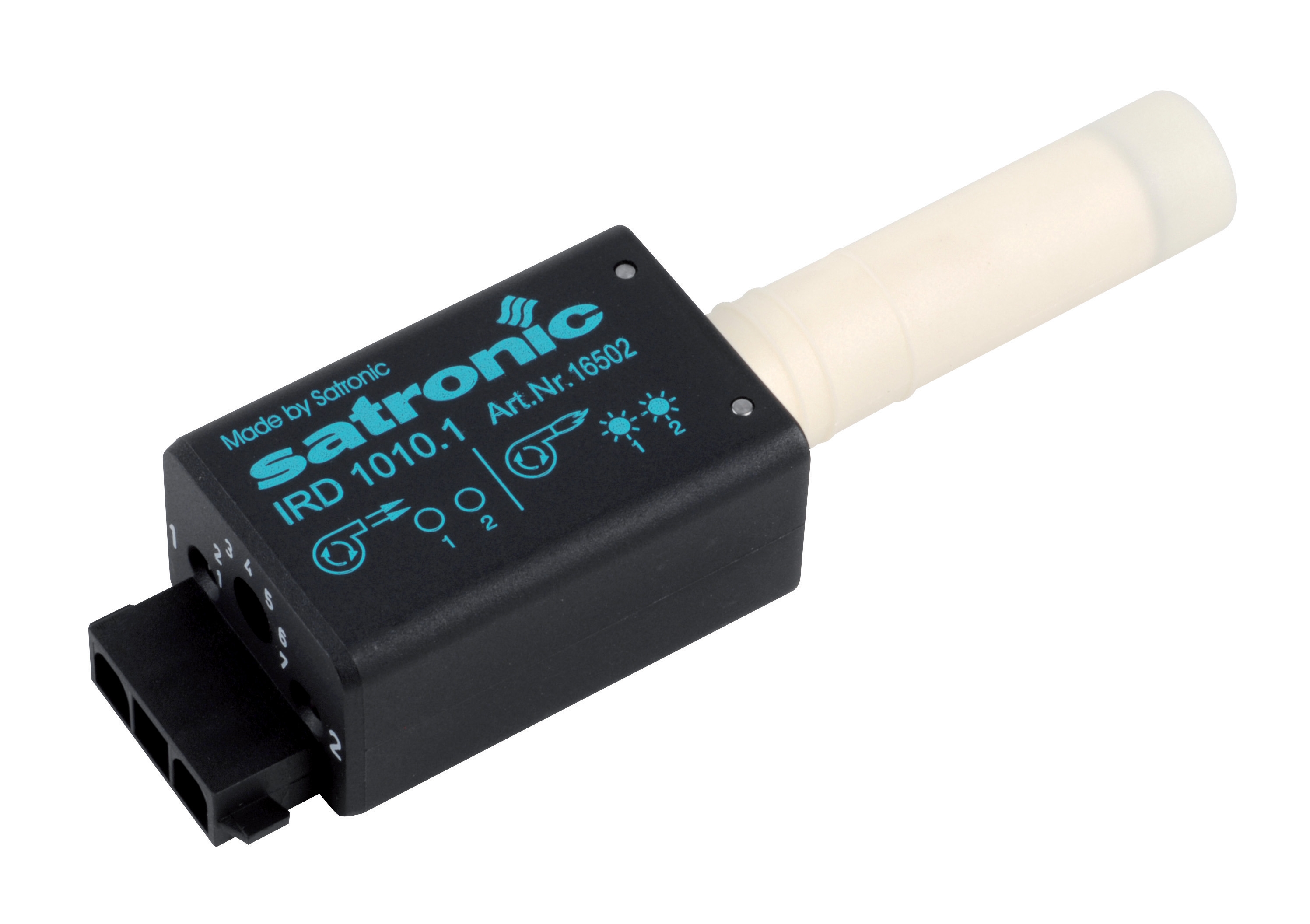
The CBM IRD 1010 infrared detector represents the industrial-grade solution for demanding environments. Infrared detectors sense radiant energy from fuel flames rather than relying on visible light characteristics. This design advantage means IRD sensors operate reliably in high ambient light conditions and through optical obstruction that would disable photocell-based systems.
Diagnostic approach: IRD failures typically manifest as gradual signal degradation, not sudden dropout. A fouled optical window reduces signal strength by 40-60% before triggering lockout. Maintenance teams should establish baseline signal strength readings during commissioning, then monitor trend data monthly. When signal strength drops 20-30% from baseline, schedule window cleaning before failure occurs. IRD sensors also include safety-rated flame presence verification—diagnostic procedures must confirm the presence/absence indicator transitions correctly during ignition sequences.
Photoresistive Cells: Cost-Sensitive Legacy Systems
Photoresistive flame sensors (often designated 8200-series variants) detect visible light spectrum emissions from combustion. These sensors offer low cost but demonstrate significant drift over 3-5 year operating windows, particularly in dusty or corrosive environments. Diagnostic procedures for photocell systems differ substantially from infrared approaches because photocell degradation correlates with environmental contamination patterns rather than optical window fouling alone.
Diagnostic approach: Photocell circuits require resistance measurement under both lit and dark conditions. A healthy photocell typically exhibits 100-500 ohms resistance under flame illumination and 5-10 megaohms in darkness. Degraded cells show inverted ratios or minimal resistance variation—classic indicators of contamination or phosphor coating breakdown. Unlike IRD detectors, photocell failures often occur suddenly rather than gradually, making trend monitoring less predictive. However, vibration-induced sensor drift represents a specific photocell failure mode absent in infrared designs—secure mounting verification becomes a diagnostic priority.
Blue-Flame Detectors: Natural Gas & LPG Burners
Blue-flame detection exploits a narrow spectral window (430nm ultraviolet region) exclusive to gas combustion chemistry. These sensors provide extremely fast response times essential for high-fire-rate gas burners. Diagnostic advantage: false flame signals are virtually impossible because non-combustion light sources rarely emit in the 430nm band.
Diagnostic approach: Blue-flame sensors typically employ phototransistor architectures requiring AC signal excitation at specific frequencies (typically 1-5 kHz). Maintenance diagnostics must verify both DC power supply integrity AND AC excitation signal presence at the sensor circuit board. Many technicians overlook the excitation signal requirement, misdiagnosing dead excitation circuits as sensor failures. Oscilloscope verification of AC signal amplitude and frequency provides definitive diagnosis.
Safety Relay Diagnostics & Real-World Control Integration
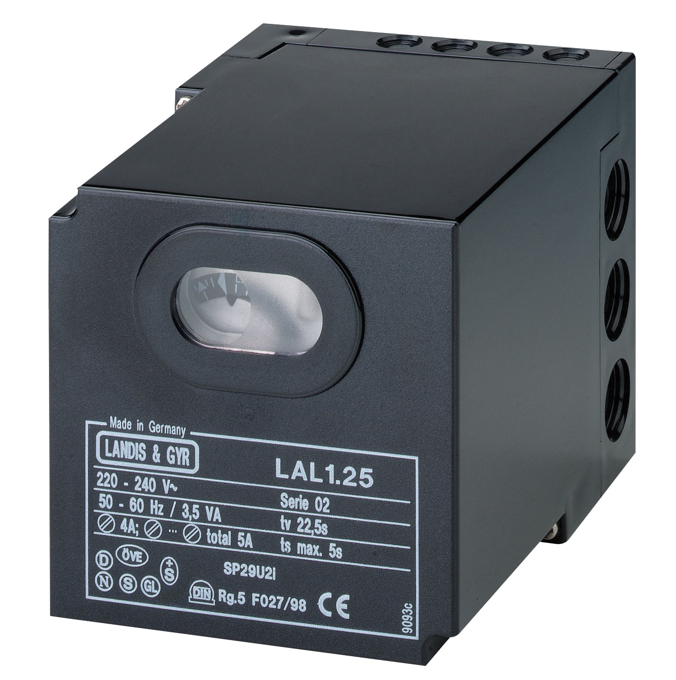
The CBM SM 592.2 relay exemplifies modern automatic gas burner control for atmospheric and fan-assisted burners, while the CBM LAL 2.14 addresses oil burner safety requirements. Both employ multi-stage lockout logic that maintenance teams must understand for effective diagnostics.
Safety relay diagnostics begin with functional testing protocols distinct from simple continuity checks. Relays must execute complete sequence cycles: ignition command → flame detection window → burner run → flame loss response → safe shutdown. Field diagnostics require either manufacturer-supplied test jigs or systematic manual cycling through each sequence state while monitoring control relay outputs.
The CBM base for GE 733 mounting platform provides consistent electrical interfaces across compatible relay modules, but diagnostic procedures must account for potential base-to-relay connection issues that mimic relay failure. Oxidation on contact surfaces, loose terminal screws, and vibration-induced micro-disconnections represent common field failures where the relay itself functions perfectly but electrical integrity fails at mounting interfaces.
Post-flame-loss response diagnostics separate nuisance lockouts from genuine safety events. When burners lock out after 5-10 seconds of run time, technicians typically assume burner malfunction. However, intermittent flame loss during burner operation often indicates control room temperature cycling affecting gas density, combustion air temperature swings, or low fuel pressure creating unstable flame geometry. Diagnostic verification requires monitoring flame signal stability over 15-30 second windows, not just confirming presence/absence during initial ignition sequence.
Real-World Application Scenarios: Diagnostics Across Burner Types & Operating Conditions
Scenario 1: Modulating Gas Burner with Intermittent Lockouts
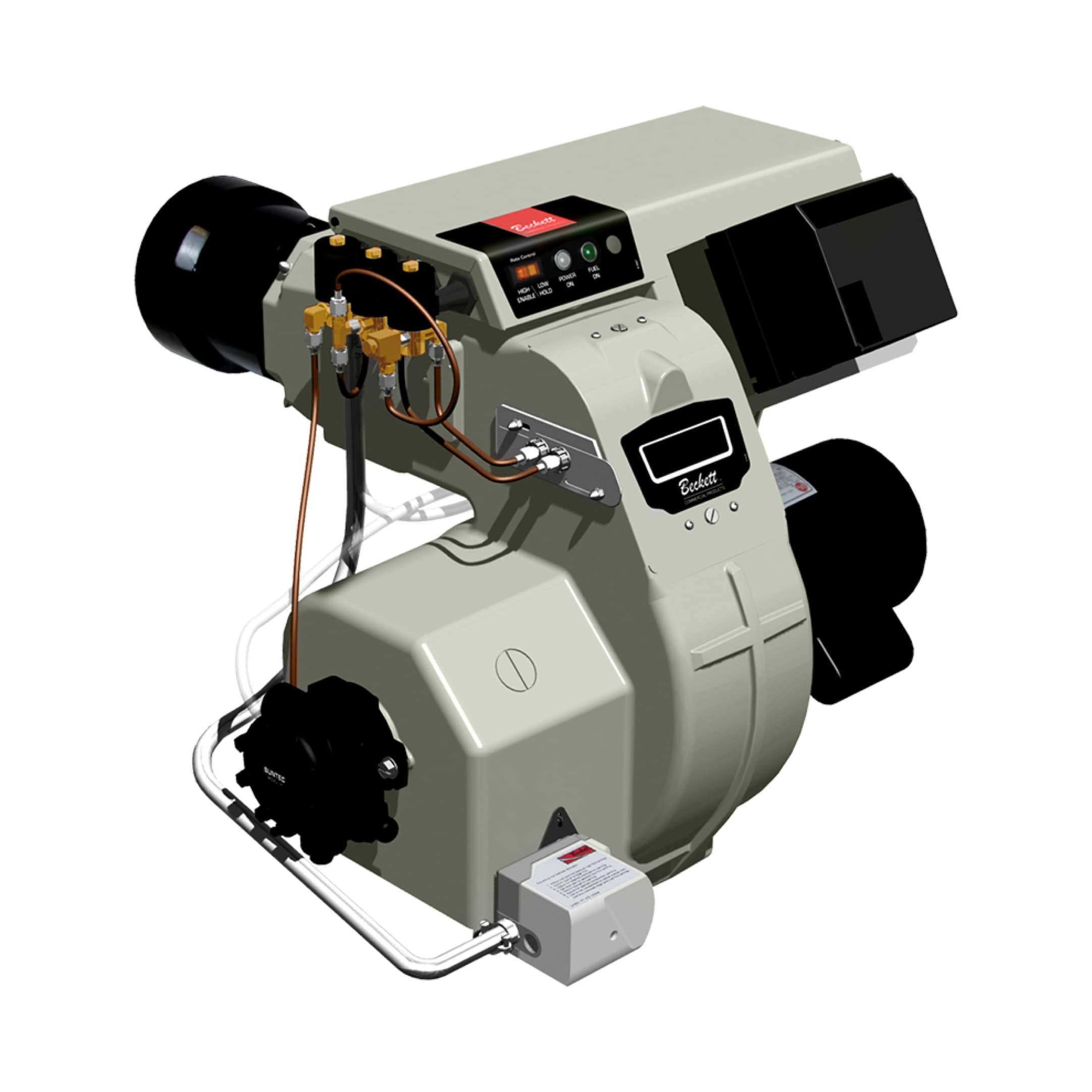
An industrial boiler equipped with the FBR GAS X5 modulating burner (operating range 69.8-349 kW) experiences lockouts during load transients. The burner fires reliably at steady-state but loses flame when load demand increases. Diagnostic approach: This pattern indicates inadequate fuel pressure during high-fire conditions, not control system failure. The GAS X5 requires minimum 27 mbar gas train pressure for natural gas operation. Technicians should verify fuel regulator performance under dynamic load conditions rather than static pressure checks. Flame signal stability during ramp sequences confirms control system function—the issue resides in fuel delivery, not detection.
Scenario 2: Legacy Oil Burner with Photocell Drift
An oil-fired steam generator with a photoresistive flame cell experiences nuisance lockouts during cold morning startups but operates reliably once combustion air temperature rises. This classic diagnostic pattern indicates photocell sensitivity drift caused by ambient temperature effects on sensor resistance baseline. Replacement with the CBM IRD 1010 infrared detector provides temperature-independent flame monitoring, eliminating seasonal lockout cycles. Retrofit diagnostic: existing control boards may require adapter harnesses because infrared signal characteristics differ from photocell outputs—electrical compatibility verification precedes hardware installation.
Scenario 3: Multi-Burner System with Selective Lockout
An industrial heating system with three identical burners experiences random single-burner lockouts while others continue operation. Suspicion falls on the affected relay, but identical relay modules in different positions suggest environmental rather than component causes. Diagnostic investigation reveals that the problematic burner occupies a position where combustion exhaust recirculation from adjacent burners reduces flame detection signal strength. Repositioning the flame sensor or adding optical isolation barriers restores stable operation—a diagnostic conclusion unreachable without understanding environmental factors beyond component-level testing.
Diagnostic Best Practices & Preventive Validation Protocols
Establish baseline performance records during commissioning. Document sensor signal strength, relay response times, and fuel pressure profiles during initial startup. These baselines become essential references for future diagnostics—without them, technicians cannot distinguish normal aging from premature degradation.
Implement monthly flame signal monitoring. Even brief monthly measurements of flame detection signal strength identify gradual degradation before catastrophic failure. This predictive approach prevents emergency service calls and unsafe burner behavior during failure transitions.
Cross-reference control responses against documented safety logic. Keep relay specification sheets accessible in the field. When unexpected lockout sequences occur, verify actual responses match documented safety sequences—mismatches often reveal wiring or component installation errors rather than device failures.
Verify electrical interfaces at relay mounting points. Loose connections at relay bases cause more field failures than relay malfunction. Include contact resistance measurement and terminal tightness verification in routine maintenance cycles.
Document all diagnostic findings and corrective actions. Building institutional knowledge prevents repeated troubleshooting of identical problems across multiple installations and supports warranty claim decisions when component replacement becomes necessary.
Conclusion: Transforming Maintenance from Reactive to Predictive
Burner control system diagnostics transform from costly guesswork into predictable processes when maintenance teams implement structured diagnostic hierarchies, understand sensor technology differences, and establish systematic validation protocols. The transition from reactive emergency service to predictive condition monitoring requires initial effort during commissioning—documenting baseline parameters, understanding safety relay logic, and training field personnel on diagnostic procedures. However, these investments yield substantial returns through reduced downtime, eliminated nuisance lockouts, and extended equipment life.
3G Electric's technical team supports maintenance operations globally with specification documentation, diagnostic consulting, and replacement components spanning the complete flame detection and burner control ecosystem. Contact us to discuss your specific control system architecture, request diagnostic support, or access detailed specification sheets for our complete relay and sensor inventory. Our field engineers can help validate diagnostic procedures specific to your burner types and operating environment, ensuring your maintenance team achieves industry-leading equipment reliability.