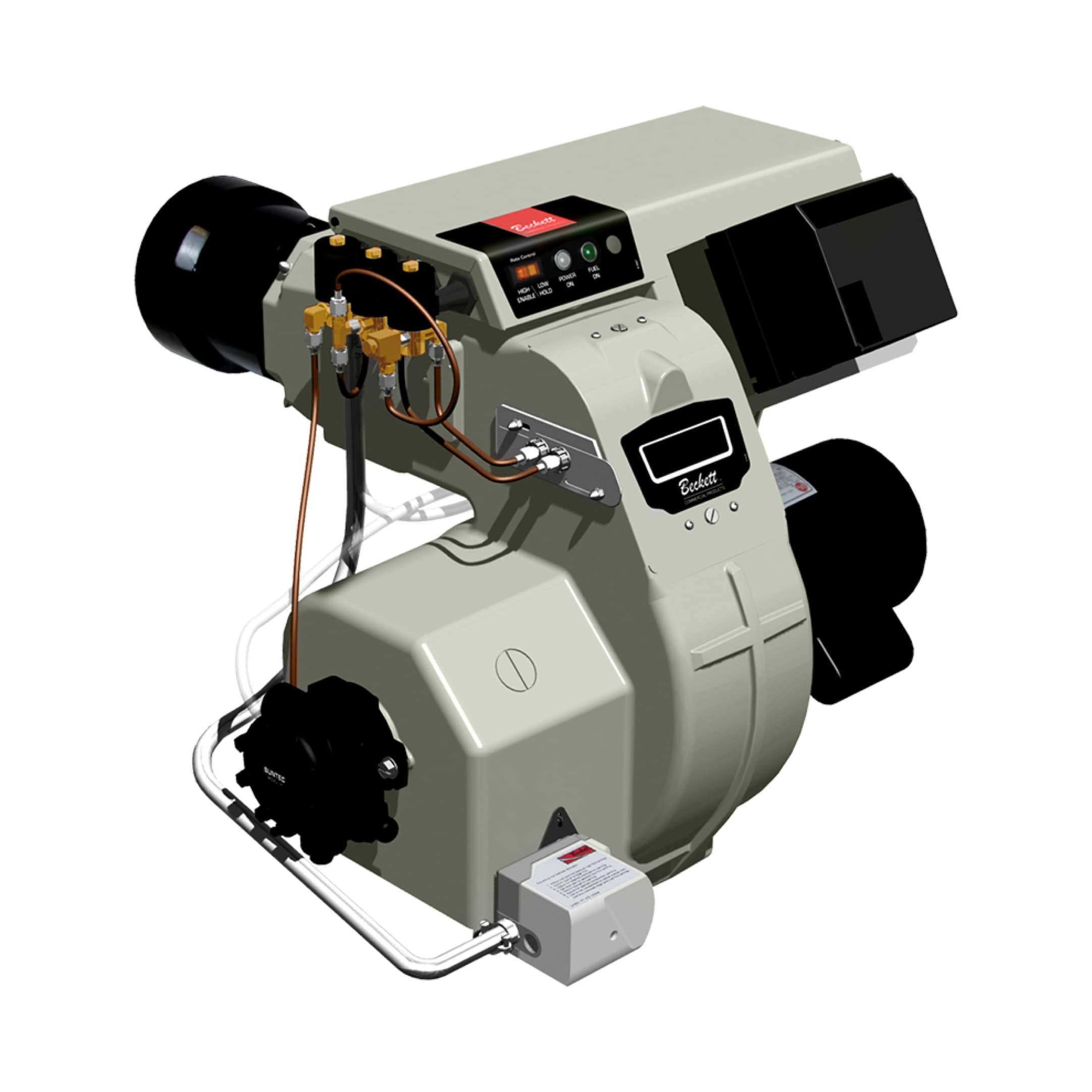
Understanding Burners & Combustion Solenoid Valve Fundamentals
Solenoid valves are electromechanical devices that control gas flow in burners & combustion systems by converting electrical signals into mechanical movement. For maintenance teams, understanding valve characteristics is essential because these components are the primary gatekeepers between your fuel supply and burner operation.
There are two main categories of solenoid valves relevant to burner control: fast-opening valves and slow-opening valves. Fast-opening solenoid valves respond immediately to electrical signals, typically operating within 50-150 milliseconds. These are critical for safety shutoff and emergency fuel cutoff scenarios. Slow-opening solenoid valves gradually increase fuel flow over a longer period (500-2000 milliseconds), enabling controlled modulation and preventing pressure shocks that can damage downstream equipment.
3G Electric has distributed industrial combustion control equipment globally for over 35 years, and our experience shows that proper solenoid valve selection reduces unplanned downtime by up to 40%. The key to reliable burner & combustion performance lies in matching valve response characteristics to your specific application requirements—a task that begins during maintenance planning.
Maintenance teams must recognize that solenoid valve selection affects not only equipment safety but also operational efficiency, fuel consumption, and system lifespan. Installing the wrong valve type can result in pressure oscillations, incomplete combustion, thermal shock to burner components, and accelerated wear on control relays.
Selecting the Right Solenoid Valve for Your Burners & Combustion Application
Fast-Opening Valves for Safety-Critical Applications
Fast-opening solenoid valves are mandatory in safety shutoff circuits and emergency fuel cutoff scenarios. When your burner control system detects a flame loss, system pressure anomaly, or operator emergency stop command, fast-opening valves must respond instantly to prevent fuel discharge into the combustion chamber or firebox.
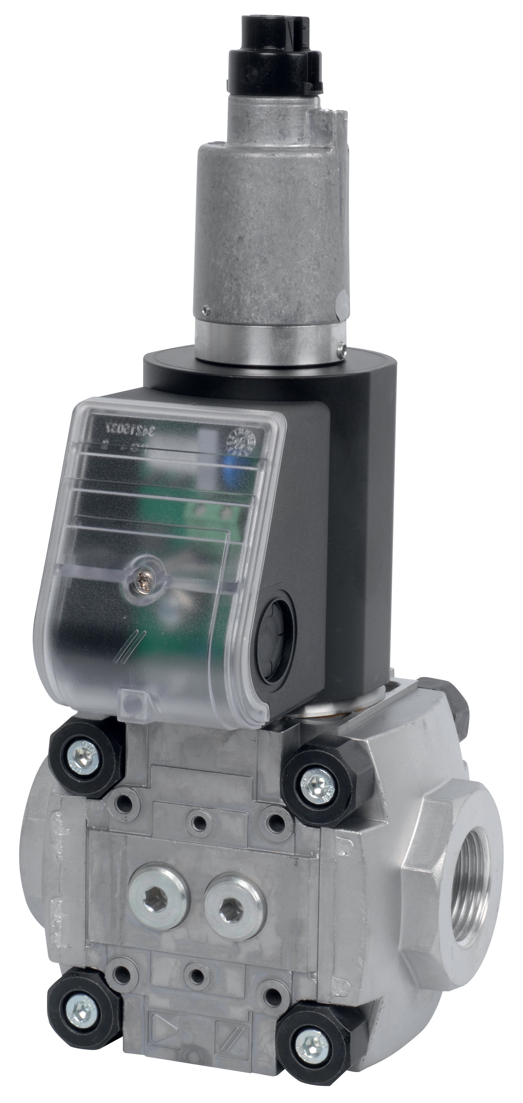
The CBM Fast gas solenoid valve VAS 110R/NW is engineered for high-speed fuel isolation in compact industrial burner applications. This valve opens and closes within 100 milliseconds, making it suitable for standalone burners and modular heating units where space and response speed are critical constraints. Maintenance teams typically specify this model for:
- Small to medium capacity burners (up to 800 kW)
- Emergency shutdown circuits
- Pilot gas supply shutoff systems
- Applications requiring rapid pressure relief
For larger combustion systems, the CBM Fast gas EV VAS 365R/NW provides identical response characteristics with increased flow capacity. This valve handles fuel flows up to 365 cubic meters per hour, making it suitable for industrial boilers, furnace burners, and large-scale heating installations. Both fast-opening valves incorporate normally-closed solenoid design, ensuring fuel isolation when de-energized—a critical safety feature that protects against uncontrolled fuel discharge during electrical failures.
Slow-Opening Valves for Modulation and Control
Slow-opening solenoid valves enable proportional fuel flow control, which is essential in modern burners & combustion systems that implement modulation for energy efficiency. These valves allow your control system to gradually adjust fuel supply based on load demand, maintaining stable flame characteristics and preventing pressure spikes.
The CBM Slow gas solenoid VAS 125R/LW is designed for proportional control in small to medium burner systems. With a response time of approximately 800-1200 milliseconds, this valve smoothly increases fuel flow while preventing abrupt pressure changes. Maintenance teams should specify this model for:
- Burners operating in modulating mode (0-100% load variation)
- Systems with sensitive flame supervision requiring stable fuel pressure
- Low to medium capacity burners with frequent load cycling
- Applications where reduced fuel consumption is a priority
For larger industrial burners requiring proportional control, the CBM Slow gas solenoid valve VAS 340R/LW provides proportional fuel metering up to 340 cubic meters per hour. This high-capacity slow-opening valve is specified for:
- Large industrial boilers and furnaces
- Dual-fuel combustion systems where gas modulation is required
- Multi-burner installations with master control circuits
- Applications requiring low-frequency oscillation and smooth load following
Installation Best Practices for Burners & Combustion Solenoid Valves
Pre-Installation Preparation and System Inspection
Before installing any solenoid valve, maintenance teams must conduct thorough system inspection and preparation:
1. Fuel Line Flushing: Flush all fuel lines with clean fuel oil or nitrogen gas (depending on fuel type) to remove manufacturing debris, scale, or accumulated contaminants. Solenoid valve failures are frequently caused by particle blockage in pilot stage orifices—a preventable issue through proper preparation.
2. Pressure System Verification: Install temporary pressure gauges upstream and downstream of the installation point. Verify that system pressure is within the solenoid valve rating (typically 0.5 to 25 bar for industrial applications). Operating pressures outside specifications will cause premature wear, erratic response, or complete valve failure.
3. Electrical Circuit Testing: Before solenoid installation, verify that your burner control circuit provides the correct voltage (24 VDC, 110 VAC, or 220 VAC—depending on valve model) with proper grounding. Use a digital multimeter to confirm voltage levels under load conditions.
4. Fuel Type Confirmation: Verify that your selected solenoid valve is rated for your specific fuel (natural gas, LPG, heavy fuel oil, or dual-fuel). Valve internal materials and orifice sizing vary by fuel type, and using the wrong valve for your fuel will result in flow control errors or sealing failures.
Mechanical Installation and Orientation
Solenoid valves are directional components with specific installation requirements:
- Flow Direction Arrow: All valves are clearly marked with a flow direction arrow on the valve body. Install the valve so fuel flows in the marked direction. Reverse flow installation will prevent valve operation and may damage internal components.
- Solenoid Coil Orientation: Mount the solenoid coil in a vertical or horizontally accessible position. Avoid installing solenoid coils pointing downward in wet environments, as condensation can enter the coil assembly and cause electrical shorts. If downward mounting is unavoidable, install a protective drain tube below the solenoid connection.
- Mounting Position: Install solenoid valves in locations protected from direct spray, excessive vibration, and temperature extremes. Industrial best practice positions solenoid valves within 2 meters of the burner control relay (such as the CBM Relay DMG 970-N MOD.03) to minimize signal transmission time and electrical noise exposure.
- Isolation and Strainers: Always install a fuel shutoff valve and strainer (100-150 micron mesh) upstream of the solenoid valve. This allows safe maintenance without full system depressurization and protects valve internals from particle contamination.
Electrical Integration with Control Relays
Solenoid valves must be properly integrated with your burner control relay system. The CBM Relay DMG 970-N MOD.03 is a flame supervision and burner control relay commonly used with industrial solenoid valve circuits.
When wiring solenoid valves to control relays, follow these maintenance-critical practices:
1. Suppress Electrical Transients: Install a surge suppressor (varistor or diode, depending on solenoid coil type) across the solenoid coil terminals. When the relay de-energizes the solenoid, the collapsing magnetic field generates high-voltage transients that degrade relay contacts and shorten coil lifespan. Proper suppression extends component life by 50-70%.
2. Use Appropriately Rated Cabling: Solenoid coils draw 0.5 to 2.0 amperes depending on valve model and coil voltage. Select control cabling rated for the maximum current plus 25% safety margin. Undersized cabling causes voltage drop, which reduces solenoid force and results in sluggish valve response or complete failure to operate.
3. Separate Signal and Power Cabling: Route solenoid control wiring at least 200mm away from main burner power cables. Cross these cables at 90 degrees only, never running them in parallel. This prevents electromagnetic interference that causes erratic valve operation and false flame detection signals.
4. Test Valve Response After Installation: After wiring is complete and before fuel system pressurization, energize the solenoid coil manually (if relay allows) and listen for the distinctive click of solenoid activation. If no click occurs, verify coil voltage and check for shorted or open winding using an ohmmeter.
Maintenance and Troubleshooting Strategies for Burners & Combustion Solenoid Valves
Preventive Maintenance Schedule
Developing a predictive maintenance program for solenoid valves significantly extends equipment life and prevents emergency shutdowns:
Monthly Inspections:
- Visual inspection for fuel leaks around solenoid valve body and connections
- Listen for abnormal sounds during burner operation (chattering or continuous buzz indicates coil or pilot stage malfunction)
- Monitor burner modulation smoothness and response to load changes
- Clean solenoid coil exterior surfaces and remove accumulated dust or moisture
- Verify electrical connections are tight and free from corrosion
- Check fuel strainer condition and replace if differential pressure gauge shows >0.5 bar pressure drop
- Conduct full fuel line flushing to remove accumulated deposits
- Remove and inspect solenoid valve pilot orifices using magnification
- Replace solenoid coil if it shows signs of moisture damage or coil insulation degradation
- Perform complete electrical system verification with pressure testing under operating conditions
Common Failure Modes and Diagnostic Procedures
Symptom: Solenoid valve does not open (no fuel flow)
- Check electrical continuity across solenoid coil terminals using an ohmmeter (typical resistance 30-150 ohms depending on coil voltage)
- Verify burner control relay is energized and providing voltage to solenoid circuit
- Remove pilot line blockage by carefully flushing with clean fuel
- If pilot stage is blocked, remove solenoid coil and use calibrated needle probe to clear orifice (typical orifice diameter is 0.5-1.2mm)
- Check fuel supply pressure—must be 2-5 bar above minimum system pressure
- Verify fuel strainer is not blocking flow (pressure drop >1.0 bar indicates strainer blockage)
- Check for air in fuel lines causing pilot stage starvation
- Measure actual fuel flow rate and compare to valve rating specification
- Internal sealing surfaces have accumulated particle deposits; do not attempt field repair
- Mark valve for replacement during next planned maintenance window
- Continue operation if leakage is minimal (<1 drop per minute) but schedule valve replacement within 30 days
- If leakage is substantial, isolate valve using shutoff valve and switch to backup burner circuit if available
- Verify correct voltage is being supplied (check for over-voltage >10% above rating)
- Ensure solenoid is de-energized when not in active burner operation (prevents continuous heating)
- Clean coil exterior to improve heat dissipation
- If coil repeatedly fails, consider upgrading to proportional solenoid with internal temperature compensation
Documentation and Compliance
Maintenance teams should maintain detailed records for all solenoid valve service:
- Installation date and valve model specification
- Service history including inspections, cleanings, and parts replacements
- Pressure readings and fuel flow measurements during annual testing
- Any failures or anomalies and corrective actions taken
These records support regulatory compliance (CE marking, ISO 9001, ASME code requirements) and provide data for equipment lifecycle cost analysis.