Understanding Controls & Safety Component Functions in Industrial Systems
Maintenance teams face a critical challenge: keeping industrial burner systems operational while ensuring safe, reliable performance. Controls & Safety systems prevent equipment damage, protect personnel, and maintain production schedules. At 3G Electric, we've supported global maintenance operations for over 35 years, and we've learned that most system failures stem from incomplete understanding of how individual components interact.
Your Controls & Safety system operates as an integrated chain where each component depends on the others. A failed solenoid valve can prevent fuel delivery, a faulty relay may cause unsafe ignition sequences, and worn pilot lights create unsafe combustion conditions. Understanding these interdependencies helps you diagnose problems faster and select appropriate replacements.
The three core component categories—control valves, switching relays, and ignition devices—work together in strict sequence. When burner startup is initiated, relays energize solenoid valves to permit fuel flow, while pilot lights establish ignition conditions. This sequence must be precise: if any component fails, the entire system defaults to safety shutdown.
Solenoid Valves: Selection and Maintenance Fundamentals
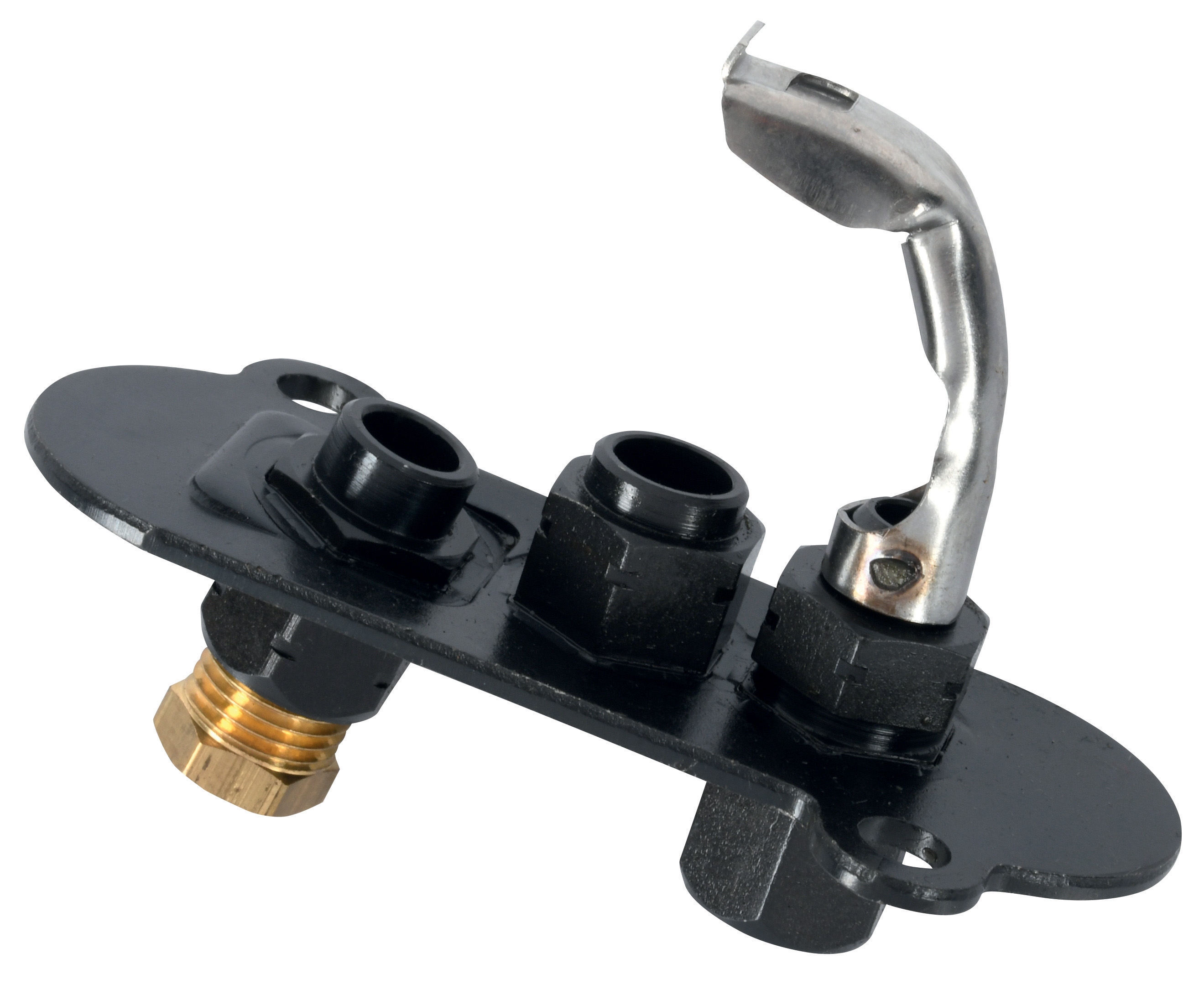
Double solenoid valves like the CBM VCS 1E25R/25R05NNWL3/PPPP/PPPP serve as the primary fuel control mechanism in industrial burners. Unlike single solenoid designs, double solenoid configurations provide redundant safety: one solenoid opens the fuel pathway while the second independently confirms closure when power is removed. This dual-safety design is industry standard for critical applications.
When selecting solenoid valve replacements, maintenance teams must verify five critical specifications:
- Flow rating and pressure range: Undersized valves create fuel starvation; oversized valves waste energy and reduce control precision
- Coil voltage compatibility: Most industrial installations use 24V DC or 120V AC—mismatched voltage causes coil failure within hours
- Response time: Critical for burners requiring rapid fuel cutoff (typically 200-400 milliseconds)
- Port size and connection type: Must match existing piping to prevent installation delays and leaks
- Material compatibility: Brass, stainless steel, and plastic bodies react differently to fuel types and temperatures
Maintenance teams should establish a solenoid valve inspection schedule: annually test coil resistance (should show 20-50 ohms), verify smooth operation without chattering or sticking, and document response times. Replace valves when coil resistance drops below 10 ohms or rises above 100 ohms—this indicates imminent electrical failure.
Common installation mistakes include mounting solenoids vertically when horizontal orientation is required, installing without proper flow direction (arrows matter), and using incorrect adapter threads. Verify your existing valve orientation before ordering replacements to ensure compatibility.
Relay Systems and Control Logic: Diagnosis and Replacement Strategies
Relays like the CBM Relay CM391.2 30.5 1.2 function as the "brain" of your Controls & Safety system, translating sensor inputs into controlled solenoid activation. A single relay orchestrates the entire startup sequence: monitoring pilot light status, confirming ignition success, managing solenoid valve timing, and implementing emergency shutdowns.
Relays operate through electromagnetic principles: when control voltage energizes the relay coil, an internal magnet pulls contacts closed, completing the circuit to solenoid valves. The relay base—such as the CBM Base LGK AGM17—provides mechanical standardization, allowing plug-and-play replacement without rewiring. Always replace relays with their designated base to maintain proper contact pressure and electrical performance.
For maintenance teams, relay diagnosis follows a logical troubleshooting sequence:
Step 1: Visual inspection - Check for burn marks on contact surfaces, corrosion on pins, and cracks in the ceramic base. These indicate imminent failure.
Step 2: Coil resistance testing - Measure ohms across the relay coil with a digital multimeter. Compare against specifications (typically 200-400 ohms). Readings below 50 ohms suggest shorted coils; above 1000 ohms indicate open circuits.
Step 3: Contact continuity testing - With the relay de-energized, contacts should show infinite resistance (open circuit). Energized contacts should show near-zero resistance. Any deviation indicates contaminated or welded contacts.
Step 4: Mechanical actuation - Manually press the relay plunger while monitoring contact closure with a multimeter. Stiff movement or incomplete contact engagement means replacement is necessary.
Relay failures rarely occur suddenly—they typically degrade over weeks, causing intermittent system shutdowns or extended ignition delays. Implement quarterly relay testing to catch degradation before it affects production. Keep spare relays on hand, as relay availability often determines system downtime length.
One critical maintenance practice: never attempt to clean relay contacts with abrasive materials or solvents. This damages the silver plating that ensures proper electrical transfer. When contacts become unreliable, replace the entire relay assembly.
Pilot Lights and Ignition Devices: Ensuring Reliable Combustion Initiation
Pilot lights serve as your system's ignition source and safety confirmation device. Models like the CBM 1-flame pilot light 0.150.082 and CBM Pilot light 1 flame 0140026 maintain continuous small flames that ignite main burner fuel while providing flame-signal feedback to the control relay.
Pilot light maintenance represents one of the highest-value tasks for maintenance teams because problems are easily diagnosed and inexpensive to resolve. A reliable pilot light flame should:
- Burn consistently blue - Yellow or orange flames indicate incomplete combustion, usually caused by air supply restrictions
- Show 1-2 mm height - Flames exceeding 5 mm are oversized and unstable; flames below 1 mm are too weak for main burner ignition
- Respond instantly to pilot valve opening - Any delay greater than 2 seconds suggests fuel supply problems
- Remain stable without flickering - Flickering indicates air turbulence or fuel pressure fluctuations
Most pilot light failures fall into three categories:
Clogged fuel orifices - Fine burner ports accumulate dust and debris over months of operation. Clean the pilot light orifice monthly using compressed air directed opposite to fuel flow direction. Never use wire or sharp tools—these enlarge the orifice and create uncontrollable fuel spray.
Electrode degradation - Spark ignition electrodes develop carbon buildup that prevents spark generation. Clean electrodes with fine sandpaper (never with grinding wheels) and verify 3-4 mm gap spacing. If electrodes are corroded or pitted, replacement is more cost-effective than cleaning.
Air shutter misalignment - The air shutter (or air vane) on pilot burners controls combustion air, preventing yellow flames. A 1/4-turn adjustment often resolves flame color issues. Mark the shutter position before adjustment so you can revert if needed.
When replacing pilot lights, verify the exact model because threaded connections vary (M18, M22, and M24 are common). Incorrect threading creates safety leaks that compromise combustion initiation. Test new pilot lights immediately after installation—they should ignite within 3 seconds of fuel valve opening.
Integrated System Diagnostics: Troubleshooting the Complete Controls & Safety Chain
The true skill in maintenance management comes from diagnosing system failures by understanding component interdependencies. A "no ignition" symptom could originate from five different sources: failed solenoid valve, faulty relay, dead pilot light, inadequate fuel pressure, or control signal loss.
Implement this diagnostic sequence when burners fail to start:
1. Verify power supply - Confirm 24V DC or 120V AC availability at the control transformer using a voltmeter. This eliminates electrical supply issues immediately.
2. Test pilot light manually - Close the solenoid valve isolation shutoff and attempt to light the pilot manually with a match or lighter. If it ignites, pilot supply lines are clear and fuel delivery works. If manual ignition fails, suspect clogged burner orifices or contaminated fuel.
3. Check solenoid valve energization - With the system in standby, measure voltage at the solenoid coil connector. Absence of voltage indicates relay failure; presence of voltage with mechanical silence suggests solenoid coil burnout.
4. Listen for relay clicks - When control signals initiate startup, listen for relay contacts closing (audible "click" sound). Silence means the relay coil isn't energizing—verify control signal voltage and relay coil resistance.
5. Verify flame signal - Modern systems use flame-sensing relays that confirm successful pilot ignition before opening main fuel valves. If the main burner won't open despite successful pilot ignition, the flame sensor may be blocked by soot or misaligned.
Document all maintenance activities in a maintenance log noting component replacement dates, test results, and adjustments made. This historical record reveals patterns—if relays fail every 8 months, electrical interference may be present; if pilot lights need monthly cleaning, fuel contamination is likely. These patterns guide preventive maintenance strategies.
Best Practices for Controls & Safety Component Management
With 35 years of experience supporting industrial operations globally, 3G Electric has identified practices that minimize downtime and extend component life:
Spare parts strategy: Maintain one complete backup set of critical components (solenoid valve, relay, pilot light) in your facility. When failures occur, you can restore operation within 15 minutes rather than waiting for emergency shipments.
Environmental protection: Controls & Safety components are sensitive to moisture, extreme temperatures, and vibration. House all relays and solenoid coils in weatherproof enclosures away from direct water exposure. Use vibration-damping mounts for solenoid valves mounted on burner frames.
Preventive testing schedule:
- Monthly: Visual inspection of pilot lights and solenoid coils
- Quarterly: Resistance and continuity testing of relays and solenoids
- Semi-annually: Full system simulation tests under load
- Annually: Component replacement on units exceeding 5 years of operation
Quality component selection: Premium components from established manufacturers cost 20-40% more initially but last 2-3 times longer and provide more reliable failure diagnostics. When budget permits, specify industrial-grade relays and solenoid valves rather than economy models.
The Controls & Safety system is not negotiable—it's the foundation of safe, reliable industrial burner operation. By understanding component functions, implementing systematic diagnostics, and following preventive maintenance practices, maintenance teams can achieve 98%+ system availability while protecting personnel and equipment.
